900 SERIES ROASTING, BAKING AND PIZZA OVEN INSTALLATION -- OPERATION -- MAINTENANCE LA SÉRIE 900 DU FOUR À RÔTIR, À CUIRE ET À PIZZA MANUEL D’INSTALLATION -- UTILISATION -- ENTRETIEN BLODGETT OVEN COMPANY www.blodgett.com 44 Lakeside Avenue, Burlington, Vermont 05401 USA Telephone (800) 331-5842, (802) 860-3700 Fax: (802)864-0183 PN 11356 Rev G (2/06) E 2003 --- G.S.
IMPORTANT WARNING: IMPROPER INSTALLATION, ADJUSTMENT, ALTERATION, SERVICE OR MAINTENANCE CAN CAUSE PROPERTY DAMAGE, INJURY OR DEATH. READ THE INSTALLATION, OPERATING AND MAINTENANCE INSTRUCTIONS THOROUGHLY BEFORE INSTALLING OR SERVICING THIS EQUIPMENT AVERTISSEMENT: UNE INSTALLATION, UN AJUSTEMENT, UNE ALTÉRATION, UN SERVICE OU UN ENTRETIEN NON CONFORME AUX NORMES PEUT CAUSER DES DOMMAGES À LA PROPRIÉTE, DES BLESSURES OU LA MORT.
THE REPUTATION YOU CAN COUNT ON UNE RÉPUTATION SUR LAQUELLE VOUS POUVEZ COMPTER For over a century and a half, The Blodgett Oven Company has been building ovens and nothing but ovens. We’ve set the industry’s quality standard for all kinds of ovens for every foodservice operation regardless of size, application or budget.
Model/Modèl: Your Service Agency’s Address: Adresse de votre agence de service: Serial Number/Numéro de série: Your oven was installed by/ Installateur de votre four: Your oven’s installation was checked by/ Contrôleur de l’installation de votre four:
Table of Contents/Table des Matières Introduction Introduction Oven Description and Specifications . . . . 2 Description et Spécifications du Four . . . . 22 Oven Components . . . . . . . . . . . . . . . . . . . . 3 Éléments du Four . . . . . . . . . . . . . . . . . . . . . 23 Installation Installation Delivery and Location . . . . . . . . . . . . . . . . . 4 Livraison et Implantation . . . . . . . . . . . . . . . 24 Oven Assembly . . . . . . . . . . . . . . . . . . . . . . 5 Montage du Four . .
Introduction Oven Description and Specifications In establishing this record, the 900 Series has set industry wide standards for excellence in baking characteristics, performance, and reliability. In its primary applications, it remains unsurpassed for product quality. Simplicity of design and quality construction throughout assure years of troublefree service if equipment is installed properly and given minimal periodic maintenance.
Introduction Oven Components Ultra Rokite Deck --- stone deck that absorbs heat from below to cook the bottom of the product. Combustion Burners --- provide heat to the baking chamber and the decks. Deck Supports --- hold the oven decks. Deflector --- diverts some of the heat from the combustion burners to the flue plates. Control Panel --- contains components to control the oven operation. Flue Plates --- located on the interior side walls of the cooking chamber.
Installation Delivery and Location DELIVERY AND INSPECTION OVEN LOCATION All Blodgett ovens are shipped in containers to prevent damage. Upon delivery of your new oven: The well planned and proper placement of your oven will result in long term operator convenience and satisfactory performance. D D Inspect the shipping container for external damage. Any evidence of damage should be noted on the delivery receipt which must be signed by the driver. Uncrate the oven and check for internal damage.
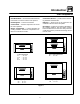
Installation Oven Assembly CASTER ATTACHMENT 1. Bolt supports to oven with 1/2---13 hex head bolts (casters with brakes should be facing front of oven.) 2. Carefully place oven onto the casters. (It will be necessary to have several persons lift oven off the pallet and set it onto the casters). Engage brakes on front casters. PACKAGING Before beginning assembly of the oven, check for all necessary components. In addition to the oven itself, legs, a proper vent, and/or other accessories may be required.
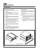
Installation Oven Assembly ULTRA ROKITE DECK 1. Slide the Ultra Rokite shelf through the door opening. Rest the shelf on the deflector and slide to the rear of the oven until it drops into the shelf support. 2. Refer to pre-heating instructions supplied with Ultra Rokite. DOUBLE SECTION ASSEMBLY 1. Place lower section in predetermined place of installation. 2. Attach the legs (and casters if applicable) as previously described. 3.
Installation Oven Assembly STEAM INJECTION 3/8” steam connection on back of oven As an optional feature, all 900 Series ovens may be supplied with steam jets for baking hard rolls, and vienna, french or other hard crusted breads. This item is also available as a kit which may be installed in the field. To a baker, steam actually means an atmosphere of water vapor.
Installation Ventilation Blodgett gas deck ovens are direct fired. Heat and flue products from the burners are introduced directly into the baking compartment. As a result, improper venting can have a detrimental effect on the baking characteristics of the oven. A properly designed ventilation system will allow the oven to function properly, while removing unwanted vapors and products of combustion from the operating area.
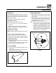
Installation Ventilation DIRECT FLUE ARRANGEMENT When the installation of a mechanically driven exhaust hood is impractical the oven may be vented by a direct flue arrangement. Flue Draft Hood WARNING!! It is essential that the direct flue be installed as follows. Incorrect installation will result in unsatisfactory baking and oven damage. The flue must be class B or better with a diameter of 6” (15 cm). The height of the flue should rise 6-8 ft (2-2.
Installation Utility Connections --- Standards and Codes THE INSTALLATION INSTRUCTIONS CONTAINED HEREIN ARE FOR THE USE OF QUALIFIED INSTALLATION AND SERVICE PERSONNEL ONLY. INSTALLATION OR SERVICE BY OTHER THAN QUALIFIED PERSONNEL MAY RESULT IN DAMAGE TO THE OVEN AND/OR INJURY TO THE OPERATOR.
Installation Gas Connection GAS PIPING A properly sized gas supply system is essential for maximum oven performance. Piping should be sized to provide a supply of gas sufficient to meet the maximum demand of all appliances on the line without loss of pressure at the equipment. Example: NOTE: BTU values in the following example are for natural gas. You purchase a Model 911 deck oven to add to your existing cook line. 1. Add the BTU rating of your current appliances.
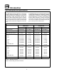
Installation Gas Connection PRESSURE REGULATION AND TESTING 900 Series ovens are rated from 20,000 to 50,000 BTU/Hr. (6.4 to 14.6 kW/Hr.) per section. Each oven has been adjusted at the factory to operate with the type of gas specified on the rating plate. DO NOT INSTALL AN ADDITIONAL REGULATOR WHERE THE OVEN CONNECTS TO THE GAS SUPPLY. Inlet Pressure Natural Propane Min Max Min Max W.C. 7.0 10.5 11.0 13.0 kPa 1.43 2.61 2.74 3.
Installation Gas Connection GAS HOSE RESTRAINT If the oven is mounted on casters, a commercial flexible connector with a minimum of 3/4” (1.9 cm) inside diameter must be used along with a quick connect device. The restraint, supplied with the oven, must be used to limit the movement of the unit so that no strain is placed upon the flexible connector. With the restraint fully stretched the connector should be easy to install and quick connect. The restraint (ie: heavy gauge cable) should be 1,000 lb.
Installation Initial Startup ADJUSTMENTS ASSOCIATED WITH INITIAL INSTALLATION Each oven, and its component parts, have been thoroughly tested and inspected prior to shipment. However, it is often necessary to further test or adjust the oven as part of a normal and proper installation. These adjustments are the responsibility of the installer, or dealer. Since these adjustments are not considered defects in material or workmanship, they are not covered by the Original Equipment Warranty.
Operation Safety Information THE INFORMATION CONTAINED IN THIS SECTION IS PROVIDED FOR THE USE OF QUALIFIED OPERATING PERSONNEL. QUALIFIED OPERATING PERSONNEL ARE THOSE WHO HAVE CAREFULLY READ THE INFORMATION CONTAINED IN THIS MANUAL, ARE FAMILIAR WITH THE FUNCTIONS OF THE OVEN AND/OR HAVE HAD PREVIOUS EXPERIENCE WITH THE OPERATION OF THE EQUIPMENT DESCRIBED. ADHERENCE TO THE PROCEDURES RECOMMENDED HEREIN WILL ASSURE THE ACHIEVEMENT OF OPTIMUM PERFORMANCE AND LONG, TROUBLE-FREE SERVICE.
Operation Oven Control CONTROL DESCRIPTION 1. AUTOMATIC SAFETY PILOT VALVE --- provides complete gas shut-off in the event of pilot failure. 2. MANUAL CONTROL VALVE --- provides manual control of gas flow to the main burner through the thermostat. 3. THERMOSTAT --- Provides regulation of oven temperature at setting selected by the oven operator. 1 OPERATION Lighting 1. Turn the MANUAL CONTROL VALVE (2) to OFF. 2. Push the red button on the AUTOMATIC SAFETY PILOT VALVE (1). 3.
Operation Suggested Times and Temperatures Product Cook Time _F _C Meats Beef Ribs 325_F 165_C Rolled, boneless Hip or rump, boneless 325_F 325_F 165_C 165_C rare - 16 mins/lb med - 20 mins/lb well - 25 mins/lb add 10 mins/lb to above times 30 mins/lb Veal Bone-in cuts Boned cuts 325_F 325_F 165_C 165_C 25 mins/lb 30 mins/lb Lamb Leg or shoulder Shoulder, boned 325_F 325_F 165_C 165_C 35 mins/lb 40 mins/lb Pork Fresh bone-in cuts Fresh boned cuts Sliced ham (2” thick) Picnic hams Hams Bac
Operation Suggested Times and Temperatures Product Cook Time _F _C Baked Vegetables Bananas Boston Beans Carrots Egg plant Macaroni Stuffed peppers Potatoes Tomatoes 350_F 250_F 400_F 350_F 350_F 350_F 400_F 350_F 175_C 120_C 200_C 175_C 175_C 175_C 200_C 175_C 15-20 mins/lb 8 hrs Until tender Until tender 15-25 mins/lb 25 mins/lb 45 - 1 1/2 hrs 15-20 mins/lb Cheese Cheese fondue Cheese loaf Toasted cheese Cheese souffle Au gratin dishes 350_F 325_F 350_F 300_F 450_F 175_C 165_C 175_C 150_C 230_C
Maintenance Cleaning and Preventative Maintenance CLEANING THE OVEN PREVENTATIVE MAINTENANCE Painted and stainless steel ovens may be kept clean and in good condition with a light oil. 1. Saturate a cloth, and wipe the oven when it is cold. 2. Dry the oven with a clean cloth. The best preventative maintenance measures are, the proper installation of the equipment and a program for routinely cleaning the ovens.
Maintenance Troubleshooting Guide POSSIBLE CAUSE(S) SUGGESTED REMEDY SYMPTOM: Strong bottoms on the bakes S S S S Too much bottom heat High gas pressure Faulty flue (strong direct vent) Product left in the oven too long S S S S Reduce cook temperature and increase time S S S S S * S S S S S S Reduce cook temperature * * Shorten cook time SYMPTOM: Uneven bakes S S S S S Poor ventilation Oven doors left open too long Improper scaling of dough Fluctuating gas pressure Warped pans Do not open doo
Maintenance Troubleshooting Guide POSSIBLE CAUSE(S) SUGGESTED REMEDY SYMPTOM: Product dried out S S S S Oven temperature too low Not using enough water in the mix Thermostat out of calibration Faulty flue (strong direct vent) S S S S Increase cook temperature S S S S Increase cook time Increase water in product mix * * SYMPTOM: Extended baking times S S S S Temperature setting too low Low gas pressure Strong ventilation Excessive door openings * * Do not open door unnecessarily *Denotes remedy
Introduction Description et Spécifications du Four En établissant ce record, les fours 900 ont établi des standards d’excellence de caractéristiques, performances et fiabilité de cuisson. Au niveau des applications primaires, la qualité des produits des fours est sans égale. La simplicité de sa conception ainsi que la qualité de sa construction assurent des années de service sans problèmes si l’appareil est monté correctement et reçoit un entretien périodique minimal.
Introduction Éléments du Four Plateforme de rokite --- plateforme de pierre qui absorbe la chaleur du bas du four pour cuire le dessous du produit. Brûleurs à combustion directe --- fournissent la chaleur à la chambre de cuisson et aux plateformes. Supports de plateforme --- supportent les plateformes du four. Déflecteur --- détourne une partie de la chaleur des brûleurs à combustion directe vers les plaques tubulaires.
Installation Livraison et Implantation LIVRAISON ET INSPECTION IMPLANTATION DU FOUR Tous les fours sont expédiés en conteneurs. A la réception de votre four Blodgett vous devez: L’implantation correcte et bien étudiée du four sera à l’avantage à long terme de l’opérateur et permettra d’obtenir un rendement satisfaisant. D D Vérifier que les emballages ne sont pas abimés.
Installation Montage du Four EMBALLAGE Avant de commencer le montage du four il faut vérifier que tous ses composants sont présents. En plus du four, lui-méme, il faut des pieds, un système de ventilation et/ou d’autres accessoires. Les fours de la série 900 sont emballés de la façon suivante: Pour les sections simples: Les pièces suivantes sont emballées dans le four: D D D Un ensemble de pieds de 70 cm avec sa boulonnerie de fixation.
Installation Montage du Four MONTAGE DE LA SECTION DOUBLE 1. Mettre la section inférieure à l’emplacement déterminé. 2. Fixer les pieds (et les roulettes, le cas échéant) comme décrit ci-dessus. 3. Prendre deux planches de 1 po. cm; en mettre une près du bord du four et l’autre planche au côté éloigné de la bague du tuyau. 4. Soulever la section supérieure et la positionner sur les planches. Pousser la section supérieure jusqu’à ce que les sections soient alignées. 5.
Installation Montage du Four INJECTION DE VAPEUR Tous les fours de la série 900 offrent l’option de gicleurs de vapeur pour cuire des petits pains et d’autres pains croustillants comme des baguettes. Ce dispositif est également disponible en kit pouvant être monté en chantier. Pour un boulanger, la vapeur est en réalité une atmosphère de vapeur d’eau.
Installation Ventilation Un système de ventilation planifié et installé est absolument nécessaire car il permet un bon fonctionnement du four tout en débarassant la surface de travail des buées et résidus de combustion. HOTTE D’ÉVACUATION TYPE VOÛTE Il y a deux méthodes de ventilation acceptables pour le four: La hotte doit être conçue pour couvrir la totalité de l’appareil à ventiler avec en plus un surplomb se 15 cm (6”) de chaque côté de l’appareil non adjacent au mur.
Installation Ventilation EN PRISE DIRECTE Quand l’installation d’une hotte aspirante mécanique est impossible ou peu pratique à réaliser, on peut ventiler le four au moyen d’une installation en prise directe. Cheminée Hotte de tirage AVERTISSEMENT!! Quand on utilise un système à prise directe il faut absolument suivre le schéma. Une installation de ventilation à prise directe qui est défectueuse donnera des résultats de cuisson peu satisfaisants et causera des dégâts prématurés aux éléments brûleurs.
Installation Branchements de Service --- Normes et Codes LES CONSEILS D’INSTALLATION ET D’ENTRETIEN CONTENUS DANS CE MANUEL NE S’ADRESSENT QU’Á UN PERSONNEL QUALIFIÉ. UN PERSONNEL NON QUALIFIE PEUT SE BLES SER ET/OU ABÎMER LE FOUR LORS DE SON INSTALLATION ET/OU SON ENTRETIEN.
Installation Branchement de Gaz CONDUIT DE GAZ Un système d’alimentation en gaz de bon calibre est essentiel pour obtenir le meilleur rendement du four. Les conduits doivent être calibrés pour fournir suffisamment de gaz pour alimenter tous les appareils sur le conduit sans perte de pression à l’équipement.
Installation Branchement de Gaz RÉGLAGE ET TEST DE PRESSION La capacité nominale de chaque compartiment Série 900 est de 20,000 jusqu’à 50,000 BTU à l’heure suivant le modèle.Tous les fours sont réglés en usine en fonction du type de gaz spécifié sur la plaque signalétique. Pression à l’entrée Gaz Naturel Gaz Propane Min Max Min Max W.C. 7.0 10.5 11.0 13.0 kPa 1.43 2.61 2.74 3.
Installation Branchement de Gaz RETENUE DU TUYAU DE GAZ Si le four est monté sur roulettes, un connecteur commercial flexible ayant un diamètre intérieur minimum de 1,9 cm (3/4”) doit être utilisé avec un dispositif de connexion rapide. La retenue, fournie avec le four, doit servir à limiter les mouvements de l’unité de façon qu’aucune tension ne soit placée sur le connecteur flexible. Quand la retenue est entièrement étendue, le connecteur doit être facile à installer et à connecter rapidement.
Installation L’Installation Initiale RÉGLAGES À FAIRE LORS DE L’INSTALLATION INITIALE Chaque four ainsi que ses composants ont été soigneusement testés et inspectés avant d’être expédiés. Cependant, il est bien souvent nécessaire de faire des vérifications et des réglages sur place au moment de l’installation initiale. Ceci est un procédé normal. De tels réglages sont sous la responsabilité du vendeur ou de l’installateur et ne sont pas imputables à des défauts de fabrication ou de matériau.
Utilisation Information de Sécurité LES INFORMATIONS CONTENUES DANS CETTE SECTION SONT DESTINÉES AU PERSONNEL QUALIFIÉ APPELÉ A UTILISER LE FOUR. ON ENTEND PAR PERSONNEL QUALIFIÉ LE PERSONNEL QUI AURA LU ATTENTIVEMENT LES INFORMATIONS CONTENUES DANS CE MANUEL, CONNAIT BIEN LES FONCTIONS DU FOUR ET/OU POSSEDE UNE EXPÉRIENCE ANTÉRIEURE DE L’EMPLOI DE L’ÉQUIPEMENT DÉCRIT.
Utilisation Oven Control 2. Appuyer sur le bouton rouge de la VALVE DE VEILLEUSE AUTOMATIQUE (1). 3. Placer une allumette ou une bougie allumée près de la veilleuse. 4. Une fois la veilleuse allumée, continuer à appuyer sur le bouton rouge pendant environ un minute puis relacher la pression. 5. Tourner la VALVE PRINCIPALE A COMMANDE MANUELLE (2) sur la position ON. 6. Régler le THERMOSTAT (3) à la température voulue. 1 2 Préchauffage 1.
Utilisation Durées et Températures Suggérées Aliment _F _C Durée Viandes Boeuf Côtes 325_F 165_C Rosbif enroulé sans os 325_F 165_C Rosbif sans os 325_F 165_C saignantes - 16 mins/lb cuites - 20 mins/lb bien cuites - 25 mins/lb ajouter 10 min/lb aux durées indiquées ci-dessus 30 mins/lb Veau Morceaux avec os Morceaux désossés 325_F 325_F 165_C 165_C 25 mins/lb 30 mins/lb Agneau Gigot ou épaule Épaule désossée 325_F 325_F 165_C 165_C 35 mins/lb 40 mins/lb Porc Morceaux frais, avec os Mo
Utilisation Durées et Températures Suggérées Aliment _F _C Durée Légumes cuits au four Bananes Haricots blancs à la sauce tomate Carottes Aubergines Macaronis Poivrons farcis Pommes de terre Tomates 350_F 250_F 400_F 350_F 350_F 350_F 400_F 350_F 175_C 120_C 200_C 175_C 175_C 175_C 200_C 175_C 15-20 mins/lb 8 hrs jusqu’à ce qu’elles soient tendres jusqu’à ce qu’elles soient tendres 15-25 mins/lb 25 mins/lb 45 - 1 1/2 hrs 15-20 mins/lb Fromage Fondue au fromage Pain de fromage Fromage fondu Soufflé a
Entretien Nettoyage et Entretien Préventif NETTOYAGE DES FOURS ENTRETIEN PRÉVENTIF Les fours peints et en acier inoxydable peuvent être conservés en bon état si on les nettoie avec une huile légère. Il doit être assuré par une installation initiale correcte et un programme de nettoyage régulier des fours. 1. Imprégner un chiffon de cette huile et frotter le four lorsque celui-ci est froid. 2. L’essuyer avec un chiffon propre et sec. Les fours n’ont pas besoin d’être graissés.
Entretien Guide de Détection des Pannes CAUSE(S) PROBABLE(S) SUGGESTION SYMPTOME: Fonds Durs: S Trop de chaleur provenant de la sole S Réduire la température et augmenter le temps S Pression de gaz élevée S Conduit d’aération défectueux (ventilation S * S * S Produit laissé trop longtemps dans le four S Écourter le temps de cuisson de cuisson directe trop forte) SYMPTOME: Cuissons Inégales S S S S S Mauvaise ventilation S Portes de four laissées ouvertes trop longtemps S Mauvais dosage de la p
Entretien Guide de Détection des Pannes CAUSE(S) PROBABLE(S) SUGGESTION SYMPTOME: Produit Désséche S Température du four trop basse S Augmenter la température de cuisson S Pas assez d’eau dans la préparation de la pâte S Augmenter la quantité d’eau dans le mélange de produit S * S Thermostat mal calibré S Conduit d’aération défectueux (ventilation S * directe trop forte) SYMPTOME: Temps de Cuisson Prolongé S S S S Mise en température trop basse S S S S Pression de gaz basse Ventilation trop forte