ACĆ500 CONVECTION OVEN INSTALLATION - OPERATION - MAINTENANCE ACĆ500 FOURS À CONVECTION MANUEL D'INSTALLATION - FONCTIONNEMENT - ENTRETIEN BLODGETT OVEN COMPANY www.blodgett.com 44 Lakeside Avenue, Burlington, Vermont 05401 USA Telephone: (802) 658Ć6600 Fax: (802)864Ć0183 PN 30930 Rev H (6/03) E 2000 - G.S.
IMPORTANT WARNING: IMPROPER INSTALLATION, ADJUSTMENT, ALTERATION, SERVICE OR MAINTENANCE CAN CAUSE PROPERTY DAMAGE, INJURY OR DEATH. READ THE INSTALLATION, OPERATING AND MAINTENANCE INSTRUCTIONS THOROUGHLY BEFORE INSTALLING OR SERVICING THIS EQUIPMENT AVERTISSEMENT: UNE INSTALLATION, UN AJUSTEMENT, UNE ALTÉRATION, UN SERVICE OU UN ENTRETIEN NON CONFORME AUX NORMES PEUT CAUSER DES DOMMAGES À LA PROPRIÉTE, DES BLESSURES OU LA MORT.
THE REPUTATION YOU CAN COUNT ON UNE RÉPUTATION SUR LAQUELLE VOUS POUVEZ COMPTER For over a century and a half, The Blodgett Oven Company has been building ovens and nothing but ovens. We've set the industry's quality standard for all kinds of ovens for every foodservice operation regardless of size, application or budget.
Model/Modèl: Your Service Agency's Address: Adresse de votre agence de service: Serial Number/Numéro de série: Your oven was installed by/ Installateur de votre four: Your oven's installation was checked by/ Contrôleur de l'installation de votre four:
Table of Contents/ Table des Matières Introduction Introduction Oven Description . . . . . . . . . . . . . . . . . . . . . 2 Description du Four . . . . . . . . . . . . . . . . . . . 26 Oven Components . . . . . . . . . . . . . . . . . . . . 3 Éléments du Four . . . . . . . . . . . . . . . . . . . . . 27 Installation Installation Delivery and Location . . . . . . . . . . . . . . . . . 4 Livraison et Implantation . . . . . . . . . . . . . . . 28 Oven Assembly . . . . . . . . . . . . . . . . . . . .
Introduction Oven Description Cooking in a convection oven differs from cooking in a conventional deck or range oven since heated air is constantly recirculated over the product by a fan in an enclosed chamber. The moving air conĆ tinually strips away the layer of cool air surroundĆ ing the product, quickly allowing the heat to peneĆ trate. The result is a high quality product, cooked at a lower temperature in a shorter amount of time.
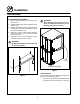
Introduction Oven Components Combustion Cover - provides access to the combustion compartment on gas ovens. Rack Supports - hold oven racks. Blower Wheel Cover - located on the back interiĆ or wall of the oven. Protects the blower wheel. Combustion Compartment - contains combusĆ tion burners on gas ovens. Blower Wheel - spins to circulate hot air in the baking chamber. Combustion Burners - provide heat to the bakĆ ing chamber on gas ovens. Convection Motor - provides power to turn the blower wheel.
Installation Delivery and Location It is essential that an adequate air supply to the oven be maintained to provide a sufficient flow of combustion and ventilation air. DELIVERY AND INSPECTION All Blodgett ovens are shipped in containers to prevent damage. Upon delivery of your new oven: D D D Inspect the shipping container for external damĆ age. Any evidence of damage should be noted on the delivery receipt which must be signed by the driver. Uncrate the oven and check for internal damĆ age.
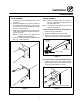
Installation Oven Assembly CASTER ASSEMBLY LEG ATTACHMENT 1. Push the oven onto a lift with the bottom of the oven down. 2. Align the threaded stud in each leg with the nut located inside each bottom corner of the oven frame. Turn the legs clockwise and tightĆ en to the nearest full turn. 3. Align the two leg plate holes in each leg with those in the oven bottom. Secure each leg usĆ ing two 1/2" bolts. NOTE: If using casters see CASTER ASĆ SEMBLY before proceeding. 4.
Installation Oven Assembly DOUBLE SECTION ASSEMBLY 1. Remove the two knock outs on the top of the bottom oven. 2. Carefully lift the upper oven and place it on the bottom oven. 3. With the side panel removed, align the holes in the bottom of the top oven with the holes in the top of the bottom oven. 4. Install the 1" long 1/2" bolt through the back hole in the bottom oven into the nut welded into the top oven. 5. Install the 1" by 1/2" bolt, 2 washers and nut in the pass through hole as shown.
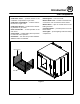
Installation Ventilation CANOPY TYPE EXHAUST HOOD On gas models the installation of a proper ventilaĆ tion system cannot be over emphasized. This sysĆ tem removes unwanted vapors and products of combustion from the operating area. A mechanically driven, canopy type exhaust hood is the preferred method of ventilation. The hood should be sized to completely cover the equipment plus an overhang of at least 6" (15 cm) on all sides not adjacent to a wall.
Installation Ventilation DIRECT FLUE ARRANGEMENT Installing the draft hood When the installation of a mechanically driven exĆ haust hood is impractical the oven may be vented by a direct flue arrangement. Ovens ordered for direct venting are supplied with a draft hood. Install the draft hood as follows: 1. Place the draft hood over the flue connector. See Figure 9. 2. Secure both ends with the sheet metal screws provided. WARNING!! It is essential that the direct flue be installed as follows.
Installation Utility Connections - Standards and Codes THE INSTALLATION INSTRUCTIONS CONĆ TAINED HEREIN ARE FOR THE USE OF QUALIĆ FIED INSTALLATION AND SERVICE PERSONNEL ONLY. INSTALLATION OR SERVICE BY OTHER THAN QUALIFIED PERSONNEL MAY RESULT IN DAMAGE TO THE OVEN AND/OR INJURY TO THE OPERATOR. U.S. and Canadian installations Installation must conform with local codes, or in the absence of local codes, with the National Fuel Gas Code, NFPA54/ANSI Z223.
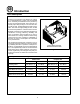
Installation Gas Connection GAS PIPING A properly sized gas supply system is essential for maximum oven performance. Piping should be sized to provide a supply of gas sufficient to meet the maximum demand of all appliances on the line without loss of pressure at the equipment. Maximum Capacity of Iron Pipe in Cubic Feet of Natural Gas Per Hour (Pressure drop of 0.5 Inch W.C.
Installation Gas Connection PRESSURE REGULATION AND TESTING ACĆ500 gas ovens are rated at 70,000 BTU/Hr. (20.5 kW/Hr.) per section. Each oven has been adĆ justed at the factory to operate with the type of gas specified on the rating plate. DO NOT INSTALL AN ADDITIONAL REGULATOR WHERE THE OVEN CONNECTS TO THE GAS SUPPLY UNLESS THE INLET PRESSURE IS ABOVE MAXIMUM. Inlet Pressure Natural Propane Min Max Min Max W.C. 4.5 10.5 11 13 kPa 1.12 2.61 2.74 3.
Installation Gas Connection GAS HOSE RESTRAINT If the oven is mounted on casters, a commercial flexible connector with a minimum of 3/4" (1.9 cm) inside diameter must be used along with a quick connect device. The restraint, supplied with the oven, must be used to limit the movement of the unit so that no strain is placed upon the flexible connector. With the restraint fully stretched the connector should be easy to install and quick connect. The restraint (ie: heavy gauge cable) should be 1,000 lb.
Installation Electrical Connection Wiring diagrams are located in the control compartment and on the back of the oven. WARNING!! This appliance is equipped with a three prong grounding type plug for your protection against shock hazard and should be plugged directly into a properly grounded three prong receptacle. DO NOT cut or remove the grounding prong from this plug. This oven is supplied for connection to a 20 amp 120 volt grounded circuit.
Installation Initial Startup NOTE: This procedure is for gas models only. The following is a checkĆlist to be completed by qualified personnel prior to turning on the appliance for the first time. j Remove the side panel. j Turn the manual shutĆoff valve, located on the front of the oven, to the ON position. j Turn the mode switch to Cook, and set the thermostat to 500_F (260_C). With the main burner on, check the following.
Operation Safety Information THE INFORMATION CONTAINED IN THIS SECĆ TION IS PROVIDED FOR THE USE OF QUALIFIED OPERATING PERSONNEL. QUALIFIED OPERATĆ ING PERSONNEL ARE THOSE WHO HAVE CAREFULLY READ THE INFORMATION CONĆ TAINED IN THIS MANUAL, ARE FAMILIAR WITH THE FUNCTIONS OF THE OVEN AND/OR HAVE HAD PREVIOUS EXPERIENCE WITH THE OPĆ ERATION OF THE EQUIPMENT DESCRIBED. ADĆ HERENCE TO THE PROCEDURES RECOMĆ MENDED HEREIN WILL ASSURE THE ACHIEVEMENT OF OPTIMUM PERFORMANCE AND LONG, TROUBLEĆFREE SERVICE.
Operation CHĆPro3 (Solid State Programmable Digital Control) COMPONENT DESCRIPTION 1. SELECTOR SWITCH - turns power to the oven on or off. Allows selection of cook or cool down modes and fan speed (if applicable). 2. LIGHTS SWITCH Ć controls interior lights. 3. TIME DISPLAY - gives cook time. 4. TIME ARROW KEYS - press to enter cook and/ or pulse times. 5. READY INDICATOR - when lit indicates the oven has reached the setpoint temperature and product may be loaded. 6.
Operation CHĆPro3 (Solid State Programmable Digital Control) MANUAL OPERATION NOTE: Press the arrow keys to change the cook time and temperature at any point duringĆ manual operation. Cook Only: 1. Turn the SELECTOR SWITCH (1) to the deĆ sired position. 2. Press the TIME ARROW KEYS (4) to enter the cook time. 3. Press the TEMPERATURE ARROW KEYS (8) to enter the cook temperature. 4. The READY INDICATOR (5) lights when the oven is at the set temperature. Load product into the oven. 5.
Operation CHĆPro3 (Solid State Programmable Digital Control) PROGRAMMING THE MANUAL KEY DEFAULT PROGRAMMING THE PRODUCT KEYS 1. Turn the SELECTOR SWITCH (1) to the deĆ sired position. 1. Turn the SELECTOR SWITCH (1) to the deĆ sired position. 2. Press the MANUAL KEY (13). The manual and fan key LEDs light. 2. Press the desired PRODUCT KEY (12). The product and fan key LEDs light. 3. Press the TIME ARROW KEYS (4) to enter the cook time. 4.
Operation Solid State Thermostat Control CONTROL DESCRIPTION 1. SELECTOR SWITCH - controls power to the oven for cook or cool down. 2. LIGHTS SWITCH Ć controls interior lights. 3. OVEN READY LIGHT - when lit indicates burner operation. When the light goes out the oven has reached operating temperature. 4. SOLID STATE THERMOSTAT Ć allows an infiĆ nite selection of temperatures from 200Ć500_F (95Ć260_C). 5. TIMER - activates an electric buzzer that sounds when the cook time expires. 1 2 3 OPERATION 1.
Operation How Cook and Hold Works With the optional COOK & HOLD feature, meat is roasted at lower temperatures for longer periods of time. This preserves flavor and tenderness and prevents over drying. There are three phases in cook and hold roasting. D D 225_ 200_ Primary Cooking - controlled by the COOK & HOLD TIMER. The meat is cooked at a low temĆ perature until approximately 2/3 done. Cooking from Stored Heat - when the primaĆ ry cook time expires, the oven automatically switches to HOLD.
Operation General Guidelines for Operating Personnel COOK TIMES AND TEMPERATURES OPERATING TIPS Preheating the oven Pans and Racks Always preheat the oven before baking or roasting. We recommend preheating 50_F (10_C) above the cook temperature to offset the drop in temperature when the doors are opened and cold product is loaded into the oven. Set the thermostat to the cook temperature after the product is loaded. Product or pan height determines how many racks are used.
Operation Suggested Times and Temperatures Product Temperature Time # Shelves Meats Hamburger Patties (5 per lb) Steamship Round (80 lb. quartered) Standing Rib Choice (20 lbs, trimmed, rare) Banquet Shell Steaks (10 oz. meat) Swiss Steak after Braising Baked Stuffed Pork Chop Boned Veal Roast (15 lbs.) Lamb Chops (small loin) Bacon (on racks in 18" x 26" pans) 400_F (205_C) 275_F (135_C) 235_F (115_C) 450_F (235_C) 275_F (135_C) 375_F (190_C) 300_F (150_C) 400_F (205_C) 400_F (205_C) 8Ć10 mins.
Maintenance Cleaning and Preventative Maintenance PREVENTATIVE MAINTENANCE CLEANING THE OVEN The best preventative maintenance measures are, the proper installation of the equipment and a proĆ gram for routinely cleaning the ovens. WARNING!! DO NOT spray the oven with water. Painted and stainless steel ovens may be kept clean and in good condition with a light oil. 1. Saturate a cloth, and wipe the oven when it is cold. 2. Dry the oven with a clean cloth.
Maintenance Troubleshooting Guide POSSIBLE CAUSE(S) SUGGESTED REMEDY SYMPTOM: Oven will not fire. S S S S S S S S S S Gas turned off. Oven not plugged in. Power switch on the control panel is off. Control set below ambient temperature. Doors are open. Turn the gas valve to ON. Plug in electrical supply cord. Set the control panel to COOK or OVEN ON. Set to desired cook temperature. Close doors. SYMPTOM: Oven does not come to ready. S The oven has not reached preheat temperature.
ACĆ500 Fours à Convection Manuel D'Installation - Utilisation - Entretien 25
Introduction Description du Four La cuisson dans un four à convection diffère de la cuisson dans un four de cuisine ordinaire en ce sens que de l'air chaud circule en permanence auĆ tour de l'aliment cuit, sous l'effet d'un ventilateur enfermé dans une enceinte spéciale. Le mouveĆ ment continu de l'air, en éliminant constamment la couche d'air froid qui se formerait autrement auĆ tour de l'aliment, permet la pénétration plus rapide de la chaleur.
Introduction Éléments du Four Porte de Combustion - permet l'accès au comĆ partiment de combustion des fours à gaz. Compartiment de Combustion - contient les brûleurs des fours à gaz. Grilles de four - cinq grilles sont fournies en équipement standard. Des grilles supplémentaiĆ res sont disponibles. Support de Grille - tient les grilles en place. Brûleurs - fournissent la chaleur à la cavité des fours à gaz. Couvercle de Ventilateur - situé sur la paroi intéĆ rieur au fond du four.
Installation Livraison et Implantation LIVRAISON ET INSPECTION Tous les fours sont expédiés en conteneurs. A la réception de votre four Blodgett vous devez: D D Vérifier que les emballages ne sont pas abimés. Toute défection dans l'emballage doit être noĆ tée sur l'accusé de reception de la marchandiĆ se; celuiĆci doit être signé par le chauffeur. Sortir le four de son emballage et vérifier son bon état.
Installation Montage du Four ASSEMBLAGE DES PIEDS 1. Coucher le four sur le dos. 2. Alignez le goujon fileté du pied sur le trou de vis prévu dans le coin avant du fond de caisse. Vissez le pied, dans le sens des aiguilles d'une montre, jusqu'au dernier tour complet possible. 3. Alignez les deux orifices de la plaque du pied sur les trous prévus au bas du four. Fixez le pied à l'aide de deux boulons de 12.7 mm (1/2 po). REMARQUE:Si des roulettes sont utilisées, voir MONTAGE DES ROULETTES avant de continuer.
Installation Montage du Four MONTAGE DE LA SECTION DOUBLE 1. Enlevez les deux pièces amovibles du dessus du section inférieure. 2. Soulevez précautionneusement la section suĆ périeure et posezĆla sur la section inférieure. 3. Enlevez le panneau latéral et alignez les orifiĆ ces prévus au bas de la section supérieure sur ceux du haut de la section inférieure. 4. Vissez le boulon de 1/2 x 1 po (12.7 x 25.6 mm) à travers l'orifice arrière de la section inférieure dans l'écrou soudé à la section supérieure. 5.
Installation Ventilation Pur les fours à gaz, un système de ventilation plaĆ nifié et installé est absolument nécessaire car il permet un bon fonctionnement du four tout en déĆ barassant la surface de travail des buées et résiĆ dus de combustion. Il y a deux méthodes de ventilation acceptables pour le four à gaz: D D Soit une hotte d'évacuation, de type voûte méĆ canique. Soit une installation à prise directe. Se reporter aux codes locaux de la ventilation.
Installation Ventilation EN PRISE DIRECTE Installation de la hotte de tirage Quand l'installation d'une hotte aspirante mécaniĆ que est impossible ou peu pratique à réaliser, on peut ventiler le four au moyen d'une installation en prise directe. Les four commandés pour la ventilation directe sont fournis avec une hotte de tirage. Installer la hotte de tirage comme suit : AVERTISSEMENT!! Quand on utilise un système à prise direcĆ te il faut absolument suivre le schéma.
Installation Branchements de Service - Normes et Codes LES CONSEILS D'INSTALLATION ET D'ENTREĆ TIEN CONTENUS DANS CE MANUEL NE S'ADRESSENT QU'Á UN PERSONNEL QUALIĆ FIÉ. UN PERSONNEL NON QUALIFIE PEUT SE BLES SER ET/OU ABÎMER LE FOUR LORS DE SON INSTALLATION ET/OU SON ENTRETIEN.
Installation Branchement de Gaz CONDUIT DE GAZ Un système d'alimentation en gaz de bon calibre est essentiel pour obtenir le meilleur rendement du four. Les conduits doivent être calibrés pour fournir suffisamment de gaz pour alimenter tous les appareils sur le conduit sans perte de pression à l'équipement. Exemple: REMARQUE:Les valeurs en BTU de l'exemple suiĆ vant sont pour le gaz naturel. Achat d'un four à convection ACĆ500 qui doit être ajouté sur la conduite de cuisson existante. 1.
Installation Branchement de Gaz RÉGLAGE ET TEST DE PRESSION Chaque section du four opère à régime nominal de 70,000 BTU/heure (20.5 kw). Tous les fours sont réglés en usine en fonction du type de gaz spécifié sur la plaque signalétique. Pression à l'entrée Gaz Naturel Gaz Propane Min Max Min Max W.C. 4.5 10.5 11 13 kPa 1.12 2.61 2.74 3.24 NE PAS INSTALLER DE RÉGULATEUR SUPPLÉĆ MENTAIRE OÙ LE FOUR SE CONNECTE SUR L'ALIMENTATION DE GAZ SAUF SI LA PRESSION D'ENTRÉE EST AU-DESSUS DU MAXIMUM.
Installation Branchement de Gaz RETENUE DU TUYAU DE GAZ Si le four est monté sur roulettes, un connecteur commercial flexible ayant un diamètre intérieur miĆ nimum de 1,9 cm (3/4") doit être utilisé avec un dispositif de connexion rapide. La retenue, fournie avec le four, doit servir à limiter les mouvements de l'unité de façon qu'aucune tension ne soit placée sur le connecteur flexible. Quand la retenue est entièrement étendue, le connecteur doit être facile à installer et à connecĆ ter rapidement.
Installation Raccordement Électrique Les diagrammes de câblage se trouvent dans le coffret de commande et à l'arrière du four. AVERTISSEMENT!! Pour votre protection contre les risques d'électrocution, cet appareil est doté d'une fiche a trois broches avec fil de terĆ re et doit etre branché directement dans une prise a trois trous adéquatement mise a la terre. Ne coupez ou ne retirez en aucun cas la broche de terre de la fiche.
Installation Mise en Marche Initiale ACĆ500 FOUR À GAZ RÉGLAGES À FAIRE LORS DE L'INSTALLATION INITIALE REMARQUE:Modèles à gaz seulement Les points de la liste qui suit doivent être contrôlés par un personnel qualifié avant la première mise en marche de l'appareil. j Enlevez les couvercles du tableau de côté. j Tourner le manuel fermer - de soupape, siĆ tuer sur le front fu four, à la ON position. j Mettez le sélecteur en position Cook (cuisson) et la temperature à 260_C (500_F).
Utilisation Informations de Sécurité Que faire en cas de panne de secteur : D Fermer tous les interrupteurs. D NE PAS tenter d'utiliser le four avant que l'élecĆ tricité soit revenue. LES INFORMATIONS CONTENUES DANS CETĆ TE SECTION SONT DESTINÉES AU PERSONNEL QUALIFIÉ APPELÉ A UTILISER LE FOUR.
Utilisation CHĆPro3 (Commande numérique programmable pour semiĆconducteurs) DESCRIPTION DES COMMANDES 1. SÉLECTEUR - met le four sous ou hors tenĆ sion. Permet de sélectionner les modes cuisĆ son ou refroidissement ainsi que, le cas échéant, la vitesse du ventilateur. 2. CADRAN DE LA MINUTERIE ć indique le temps de cuisson. 3. TOUCHES FLÉCHÉES DE LA MINUTERIE ć utiliser ces touches pour entrer le temps de cuisson et / ou d'impulsion. 4.
Utilisation CHĆPro3 (Commande numérique programmable pour semiĆconducteurs) OPÉRATION MANUELLE REMARQUE:Appuyer sur les touches fléchées pour changer le temps et la tempéraĆ ture de cuisson à n'importe quel moĆ ment durant l'opération manuelle. Cuisson seulementĄ: 1. Régler le SÉLECTEUR (1) sur la position désirée. 2. Appuyer sur les TOUCHES FLÉCHÉES DE LA MINUTERIE (3) pour entrer le temps de cuisson. 3. Appuyer sur les TOUCHES FLÉCHÉES DE TEMPÉRATURE (7) pour entrer la températuĆ re de cuisson. 4.
Utilisation CHĆPro3 (Commande numérique programmable pour semiĆconducteurs) 8. Lorsque le temps d'impulsion touche à sa fin, les deux cadransse mettent à clignoter et une alarme retentit. Appuyer sur la TOUCHE ARRÊT (15) pour arrêter l'alarme. 9. Retirer l'aliment du four. Arrêt du fourĄ: 1. Régler le SÉLECTEUR (1) sur la position OVEN OFF. FONCTIONNEMENT DES OPTIONS PAR DÉFAUT DE LA TOUCHE CUISSON MANUELLE 1. Régler le SÉLECTEUR (1) sur la position désirée. 2.
Utilisation CHĆPro3 (Commande numérique programmable pour semiĆconducteurs) PROGRAMMATION DE LA TOUCHE DE PRODUIT FONCTIONNEMENT DE LA TOUCHE DE PRODUIT 1. Régler le SÉLECTEUR (1) sur la position désirée. 1. Régler le SÉLECTEUR (1) sur la position désirée. 2. Appuyer sur la TOUCHE DE PRODUIT (11) désirée. Les voyants DEL de la touche maĆ nuelle et du ventilateur s'allument. 2. Appuyer sur la TOUCHE DE PRODUIT (11) désirée. Les voyants DEL des touches pertiĆ nentes s'allument. 3.
Utilisation Commandes à SemiĆConducteurs DESCRIPTION DES COMMANDES 1. SÉLECTEUR Ć commande le fonctionnement du four en mode de cuisson ou de refroidisseĆ ment (COOL DOWN). 2. TOUCHE DU LUMIERE (LIGHTS) Ć commanĆ de des lumières d'interior. 3. VOYANT D'ÉTAT DU FOUR Ć indique l'allumaĆ ge du brûleur. Le voyant s'éteint lorsque le four atteint la température demandée. 4.
Utilisation Principe de la Fonction de Cuisson et Maintien Avec la fonction en option de CUISSON ET MAINĆ TIEN, la viande peut être rôtie à des températures plus basses pendant de plus longues périodes de temps. Ceci préserve le goût et la tendreté de la viande et l'empêche de se dessécher. Il y a trois phases pour rôtir en cuisson et maintien.
Utilisation Consignes Générales à l'Intention des Utilasateurs TEMPS ET TEMPÉRATURES DE CUISSON un maximum de 17 plaques à petits pains de 18 x 26 po (457 x 660 mm). Préchauffage du four Toujours préchauffer le four avant de cuire ou de rôtir. Nous recommandons un préchauffage de 10_C (50_F) supérieur à la température de cuisĆ son pour compenser la chute de température quand les portes sont ouvertes et qu'un produit froid est chargé dans le four.
Utilisation Durées et Températures Suggérées Aliment Température Durée Étagères Viandes Hamburgers (5 pâtés/lb) Gîte (80 lbs, en quartiers) Côte de choix (20 lbs, dégraissé, saignant) ContreĆfilet (portions de 10 oz) Steak suisse après braisage Côtelette de porc farcie Rôti de veau désossé (15 lbs) Côtelettes d'agneau (premières) Lard (sur grilles en plats de 18 x 26 po) 400_F (205_C) 275_F (135_C) 235_F (115_C) 450_F (235_C) 275_F (135_C) 375_F (190_C) 300_F (150_C) 400_F (205_C) 400_F (205_C) 8Ć10 m
Entretien Nettoyage et Entretien Préventif NETTOYAGE DES FOURS ENTRETIEN PRÉVENTIF AVERTISSEMENT!! Débranchez le four de la prise de courant avant son nettoyage ou son entretien. Les fours peints et en acier inoxydable peuvent être conservés en bon état si on les nettoie avec une huile légère. 1. Imprégner un chiffon de cette huile et frotter le four lorsque celuiĆci est froid. 2. L'essuyer avec un chiffon propre et sec.
Entretien Guide de Détection des Pannes CAUSE(S) PROBABLE(S) SUGGESTION SYMPTOME: Le four ne s'allume pas. S Le gaz est fermé. S Tourner la vanne de gaz sur ON (MARCHE). S Le four n'est pas branché. S Brancher le fil dans la prise. S L'interrupteur électrique du paneau de contrôle S Régler le panneau de contrôle sur COOK (CUISĆ S est sur arrêt. Contrôle réglé auĆdessous de la température ambiante. S Portes ouvertes. SON) ou OVEN ON (FOUR MARCHE). S Régler la température désirée. S Fermer les portes.
INSERT WIRING DIAGRAM HERE PLACER SCHÉMA DE CÂBLAGE ICI