IMPORTANT WARNING: IMPROPER INSTALLATION, ADJUSTMENT, ALTERATION, SERVICE OR MAINTENANCE CAN CAUSE PROPERTY DAMAGE, INJURY OR DEATH. READ THE INSTALLATION, OPERATING AND MAINTENANCE INSTRUCTIONS THOROUGHLY BEFORE INSTALLING OR SERVICING THIS EQUIPMENT FOR YOUR SAFETY Do not store or use gasoline or other flammable vapors or liquids in the vicinity of this or any other appliance. The information contained in this manual is important for the proper installation, use, and maintenance of this oven.
THE REPUTATION YOU CAN COUNT ON For over a century and a half, The Blodgett Oven Company has been building ovens and nothing but ovens. We’ve set the industry’s quality standard for all kinds of ovens for every foodservice operation regardless of size, application or budget. In fact, no one offers more models, sizes, and oven applications than Blodgett; gas and electric, full-size, half-size, countertop and deck, convection, Cook’n Hold, Combi-Ovens and the industry’s highest quality Pizza Oven line.
iv
TABLE OF CONTENTS TABLE OF CONTENTS (Continued) Page Page SECTION 1 I. MODEL IDENTIFICATION .............................................. 1 SERIES BE2136 ELECTRICAL SPECIFICATIONS .......... 2 II. PRINCIPLE OF AIR FLOW ............................................. 3 A. Heat Transfer and How It Works .............................. 3 II. PRINCIPLE OF AIR FLOW (Continued) ........................ 4 B. Air Fingers ................................................................. 4 III. COMPONENT FUNCTION ..
NOTES vi
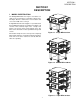
SECTION 1 DESCRIPTION SECTION 1 DESCRIPTION I. MODEL IDENTIFICATION The Blodgett BE2136-Series may be used either as a single oven or stacked for use as double or triple ovens. The major difference between the oven models in this series is the width of the conveyor. A single BE2136-Series Oven (Figure 1-1) is mounted on a base pad with legs and casters. A double oven (Figure 1-2) consists of two, stacked, single ovens. A triple oven (Figure 1-3) consists of three stacked single ovens.
SECTION 1 DESCRIPTION BE2136 SERIES OVEN SPECIFICATIONS Table 1-1: Dimensions Overall Height: single oven with 17-1/2" (446mm) legs 43-1/2" (1105mm) double oven with standard 17-1/2" (446mm) legs 63" (1600mm) double oven with optional 20-1/2" (521mm) legs 66" (1676mm) double oven with optional 25-1/2" (648mm) legs 71" (1803mm) triple oven with 6" (152mm) legs 71" (1803mm) 46" (1168mm) with standard 60"/1524mm conveyor 61" (1549mm) with optional 56"/1422mm conveyor 57" (1447mm) with optional 7
SECTION 1 DESCRIPTION II. PRINCIPLE OF AIR FLOW The fan-style blower draws air into the oven plenum where it is heated. The blower then pushes the hot air through the air fingers into the baking chamber. Each air finger contains an inner plate and outer plate that form the hot air into jets, distributing it across a conveyor belt on which the food product rides. Air is then pulled back into the blower and the process continues. The curving, black arrows of Figure 1-4 show this air flow.
SECTION 1 DESCRIPTION II. PRINCIPLE OF AIR FLOW (Continued) B. Air Fingers Series ovens used to bake pizza have four bottom fingers and two top fingers. For special product baking requirements, a number of other styles of fingers and finger arrangements are available from the factory. The BE2136-Series Ovens are conveyorized ovens that employ vertical jets of hot air streaming from air fingers (Figure 1-5) to give uniform, intense heating.
SECTION 1 DESCRIPTION III. COMPONENT FUNCTION (Figure 1-6) Figure 1-6.
SECTION 1 DESCRIPTION III. COMPONENT FUNCTION A. Conveyor Motor and Conveyor Belt The conveyor belt is driven by a variable-speed electric motor (Figure 1-7) operating through a gear reducer. The motor speed is controlled by a digital control. The stainless-steel wire belt can travel in either direction at variable rates ranging from 3 minutes to 30 minutes; this is the time that a product can take to pass through the oven. B. Blower Fan The blower fan is located at the rear of the oven.
SECTION 1 DESCRIPTION Figure 1-8.
SECTION 1 DESCRIPTION F2. Blank Plates 1. Blank Plates- The Blank Plates are available to install on the plenum where an air finger is not required. Half Blank Plate Outer Plate Blank Plate Inner Plate Finger Manifold Assembly Baffle Figure 1-9. Blank Plates (two sizes) and an Air Finger.
SECTION 2 INSTALLATION SECTION 2 INSTALLATION NOTE: The oven, when installed, must be electrically grounded in accordance with local codes, or in the absence of local codes, with the National Electrical Code (NEC), or ANSI/NFPA70. I. UNLOADING Your Blodgett BE2136-Series Oven is shipped partially assembled. It will arrive in a carton on a crate. Carton size for a BE2136-Series Oven is: NOTE 58″ (2134mm) Long × There must be adequate clearance between the oven and any adjacent combustible construction.
SECTION 2 INSTALLATION BE2136 OVEN INSTALLATION REQUIRED KITS AND EQUIPMENT TYPE OF INSTALLATION BE2136 Single Oven BE2136 Double Oven BE2136 Single Oven Installation Kit P/N 44919 45529 (CE) BE2136 Double Oven Installation Kit P/N 44920 45530 (CE) BE2136 Triple Oven Installation Kit P/N 44921 45531 (CE) 1 BE2136 Additional Cavity Installation Kit P/N 44974 45532 (CE) 1 1 2 BE2136 Triple Oven 1 10 3
SECTION 2 INSTALLATION Figure 2-1 - Installation Kit I. INSTALLATION KIT - see Figure 2-1 Item 1 2 3 4a Qty. Single Oven 1 2 1 4 Qty. Double Oven 1 2 1 4 Qty. Triple Oven 1 2 1 -- Part No. 48605 3A80A8801 42893 42890 Inc. with domestic ovens? Yes Yes Yes Yes Inc.
SECTION 2 INSTALLATION Figure 2-5.
SECTION 2 INSTALLATION Figure 2-6.
SECTION 2 INSTALLATION 1 ELECTRICAL JUNCTION BOX 2 RECOMMENDED MINIMUM CLEARANCES: Rear of Oven to Wall - 6″ (150mm) Non-control End of Oven to Wall - 0″ Control End of Oven to Wall - 0″ 2 2 2 1 Figure 2-7. MODEL BE2136 TRIPLE OVEN DIMENSIONS RESTRAINT CABLE INSTALLATION Install the restraint cable assembly on the oven, as shown in Figure 2-6. Figure 2-8.
SECTION 2 INSTALLATION UTILITY ROUGH-IN ROUGH-IN DIMENSIONS DIMENSIONS AND AND POSITIONING POSITIONING UTILITY FOR OVENS FORBE2136-SERIES PS540-SERIES OVENS 5 WARNING DO NOT USE CONDUIT OR GAS LINE FOR GROUND CONNECTION. ON 6 OFF 2 3 1 24" 610mm 2 CAUTION 6 IT IS REQUIRED THAT THE OVEN BE PLACED UNDER A VENTILATION HOOD FOR ADEQUATE AIR SUPPLY AND VENTILATION.
SECTION 2 INSTALLATION II. VENTILATION GUIDELINES VENTILATION HOOD A mechanically driven ventilation system is required for the BE2136 Series Blodgett conveyorized electric ovens. The minimum hood canopy dimensions are outlined below. The rate of air flow exhausted through the ventilation system is generally between 1400 and 2500 cu. ft./min. (40 and 70 m3/min), but may vary depending on the oven configuration and hood design.
SECTION 2 INSTALLATION III. ELECTRICAL CONNECTION INFORMATION FOR BE2136-SERIES OVENS. IV. ELECTRIC SUPPLY FOR ELECTRICALLY HEATED OVENS Power requirements for electrically heated ovens are usually 208 - 240VAC, 3-phase, 4-wire (3 ‘hot’, 1 ground), although ovens built for export can have power requirements of 380VAC and 480VAC. (These ovens have a 5wire system.) A 2″ (51mm) diameter cutout/hole in the back of the machinery compartment provides access for the electrical supply connections.
SECTION 2 INSTALLATION VI. CONVEYOR REAR STOP AND END STOP INSTALLATION Locate the conveyor rear stop and end stop in the installation kit. Install the rear stop and end stop at the exit end of the oven. See Figure 2-13. Figure 2-13.
SECTION 3 OPERATION SECTION 3 OPERATION I. CONTROL FUNCTIONS Figure 3-1. BE2136-Series Oven Control Functions WARNING A possibility of injury from rotating parts and electric shock exists in this oven. Never disassemble or clean the oven with the BLOWER/HEAT switch or any other oven control turned “ON” or “I”. Turn “OFF” or “O” and lockout or tagout all electric power to the oven before attempting to clean or service this oven.
SECTION 3 OPERATION II. COMPONENT INFORMATION AND LOCATION (Figures 3-1 and 3-2) burner cannot light, if the air switch does not sense air flow off the main blower fan. A. Door Safety Switch C. Heat Switch The Door Safety Switch is located at the lower left side of control panel opening. Opening the control panel door permits this switch to open, disconnecting power to all electrical controls. Turning the HEAT switch to “ON” or“I” will initially set up the oven purge circuit.
SECTION 3 OPERATION E. Conveyor The on-off switch for the conveyor motor is on the control panel. Also on the control panel is the digital conveyor speed control. The digital control can be adjusted from 3 min. to 30 min. bake time (conveyor speed). Refer to Figure 3-3. Conveyor speed is measured by the amount of time it takes for an item to go through the bake chamber of the oven. MEASURING CONVEYOR SPEED. See Figures 3-4 and 3-5. Figure 3-3.
SECTION 3 OPERATION 4. Set the temperature controller to the desired baking temperature. See section on bake times to determine desired temperature. WARNING OVEN MUST BE KEPT CLEAR OF COMBUSTIBLES AT ALL TIMES. NOTE: For complete temperature controller operation instructions refer to Step C. III. STEP-BY-STEP OPERATION 5. Turn the HEAT switch (Figure 3-6) to the “ON” or “I” position. This completes a circuit to supply electric power to the electric heating system.
SECTION 3 OPERATION D C B A Figure 3-6. Control Panel LOCATION AND DESCRIPTION OF CONTROLS A. B. "BLOWER/HEAT" Switch: Turns the blower and cooling fans on and off, as well as, the gas burner system. The gas burners will activate shortly after the BLOWER/HEAT switch is turned on. The Temperature of the oven will be regulated by the temperature controller. "CONVEYOR" Switch: drive motor on and off. Turns the conveyor Conveyor Speed Controller: Adjusts and dis- D.
SECTION 3 OPERATION II. NORMAL OPERATION - STEP-BY-STEP A. DAILY STARTUP PROCEDURE 8. 1. Check that the circuit breaker/fused disconnect is in the on position. Check that the window is closed. B. DAILY SHUTDOWN PROCEDURE 2. Turn the "BLOWER/ HEAT" ( )( ) switch to the “ON” ("I") position. 3. Turn the "CONVEYOR" ( ) switch to the “ON” ("I") position. 4. 5. 6. 7.
SECTION 3 OPERATION Display "HEAT ON" Light Shows the Set Point or the Actual Temperature in degrees Fahrenheit (F) or Celsius (C). Lights when the burner is in operation. "SP LOCK" Light Lights when the set point is locked out from changes. This setting can only be changed by service personnel. "SET PT" (setpoint) Light Lights when the set point is shown in the display. OVERTEMP Light "ACTUAL TEMP" Light Lights when the oven temperature is greater than 650°F (343°C).
SECTION 3 OPERATION IV. QUICK REFERENCE: TROUBLESHOOTING SYMPTOM PROBLEM SOLUTION The oven temperature exceeded 650°F (343°C), and the burner was automatically shut down. • Follow the procedures under Daily Shutdown Procedures in this section to shut down the oven. Contact your Middleby Marshall Authorized Service Agent to determine and correct the cause of the condition to prevent damage to the oven.
SECTION 4 MAINTENANCE SECTION 4 MAINTENANCE WARNING Possibility of injury from rotating parts and electrical shock exist in this oven. Turn off and lockout or tagout electrical supply to oven(s) before attempting to disassemble, clean or service oven(s). Never disassemble or clean the oven with the blower switch or any other part of the oven turned on. WARNING Before performing any maintenance work or cleaning, turn main power switch off.
SECTION 4 MAINTENANCE I. MAINTENANCE - DAILY D. Crumb Pans (Figure 4-2) A. Exterior Remove and clean the crumb pan at each end of the oven. Each crumb pan can be removed by sliding it out, as shown in Figure 4-2. Reinstall the crumb pans after cleaning. Everyday you should clean the outside of the oven with a soft cloth and mild detergent. E. Window WARNING The window can be cleaned daily while it is in place. Never use a water hose or pressurized steam cleaning equipment when cleaning the oven. B.
SECTION 4 MAINTENANCE deposits use a non-caustic cleaner that will not react with the aluminized finger manifold surfaces. II. MAINTENANCE - MONTHLY NOTE: The oven interior may require cleaning more than once a month depending on the volume of baking. To clean the interior, you have to disassemble some parts of the oven.
SECTION 4 MAINTENANCE 4. Remove conveyor drive chain cover as shown. 5. Remove tension from drive chain by lifting and pushing the conveyor slightly into the oven. Remove drive chain from conveyor drive sprocket as shown. NOTE: The split belt conveyor assembly can only be removed from the drive end of the oven. 6. Begin sliding conveyor out of the oven as shown. Figure 4-4. Figure 4-7. 7. Continue sliding the conveyor completely out of the oven, fold it in half and then place it to the side for cleaning.
SECTION 4 MAINTENANCE B. Air Fingers Disassembly For Cleaning 1. As the air fingers are removed use a felt pen to mark all parts of the fingers. This includes the finger manifold, inner plate and the outer plate (refer to Figure 1-9). If a blank or choke plate is used, mark that plate also. Fingers are marked in the order shown; as viewed from the front of the oven. (The marks for an upper oven should be preceded with a “U”, example UB1, UT2, etc.) T1 T2 T3 T4 B1 B2 B3 B4 Standard Fingers 2.
SECTION 4 MAINTENANCE 6. To remove the inner plate, pull the plate out and then up. D. Reassembly of Air Fingers 1. Air fingers are made up of one inner plate, one outer plate and the finger housing manifold. Be sure to match up the markings (T1, T2, T3, etc.) on all the parts of the air fingers as you are reassembling. Figure 4-12. 7. The outer finger plate is stainless and may be cleaned by either soaking in a hot, strong detergent solution or using a caustic cleaner.
SECTION 4 MAINTENANCE 4. Replace the air fingers by pushing in at the back side. Remember to replace them according to the numbers marked on them when they were removed. They must go back in the same way they came out. IMPORTANT: When inserting fingers the tab on the outer plate must be in the groove as shown in Figure 4-18. There is a blocking tab on the outside of the groove which will prevent inserting the finger in the groove if the outer plate is moved away from the flange of the finger manifold.
SECTION 4 MAINTENANCE 5. Install fingers and blank plates correctly with edges interlocked and no space between edges. Incorrect - Too Much Space Top Finger Blank Plate Tab on Outer Plate of Finger Located in Groove Incorrect - Too Much Space Top Finger Blank Plate Tab on Outer Plate of Finger Located in Groove Correct Edges Overlap Completely Top Finger Blank Plate Tab on Outer Plate of Finger Located in Groove Figure 4-19.
SECTION 4 MAINTENANCE E. Reinstall End Plugs 1. Reinstall lower end plug. Be sure to tighten two wing screws on the end plug. 2. Reinstall conveyor. 3. Reinstall upper end plug. Be sure to tighten two wing screws on the end plug. Figure 4-20. Figure 4-21.
SECTION 4 MAINTENANCE F. Conveyor Reassembly Into Oven G. Checking Conveyor Belt Tension 1. Lift conveyor and position it in oven as shown. WARNING NOTE: Conveyor assembly may be inserted into either end of oven. If it is to be installed from the non-drive end of the oven the drive sprocket assembly must be removed as shown in conveyor disassembly section. Oven conveyor belt must be cool when adjusting belt. Do not adjust belt if HOT. 1.
SECTION 4 MAINTENANCE H. Conveyor Belt Link Removal 4. Unhook the link to be removed. 1. Using long nose pliers, an entire link can be removed with the conveyor assembly either in or out of the oven. Position master links at end of conveyor as shown in Figure 4-25. 5. Pull up on the belt link section and remove. Do not discard the link removed as it may be used for making spare master links. NOTE: If a section of the conveyor belt is being replaced it should be done now.
SECTION 4 MAINTENANCE 6. Reconnect the inside master links (Figure 4-30.) I. Replacing Conveyor Belt If a section of the conveyor belt needs replacing it can be done with the conveyor assembly either in or out of the oven. The section of the conveyor belt furnished with the oven in the installation kit may then be used to replace a section. Follow the preceding procedure “H. Conveyor belt link removal” which outlines the disassembly procedure. J. Attaching Drive Chain 1.
SECTION 4 MAINTENANCE 4. Reassemble conveyor drive chain cover and then reassemble the bottom cover to the drive chain cover. III. MAINTENANCE - EVERY 3 MONTHS Install both upper end plugs. WARNING Shut OFF all electrical power and lock/tag out the switch before attempting maintenance work. Shut OFF gas supply to oven. NOTE: It is recommended that the 3-month maintenance be performed by an authorized Middleby Marshall technician. A.
SECTION 4 MAINTENANCE B. Electrical Terminals C. Ventilation Open the control cabinet door by removing the three screws from the control cabinet door. Tighten all electrical control terminal screws including the electrical contactor terminal screws as shown in Figure 4-37. Check that the air circulation throughout the oven is not blocked and is working properly. Figure 4-37. Figure 4-38.
SECTION 4 MAINTENANCE D. Split-belt Conveyor Shaft Cleaning 4. Drop the idler shaft assembly clear of the frame through the front frame slot. It is very important that the split-belt conveyor drive and idler shafts are removed from the conveyor frame for cleaning and lubrication. CAUTION Use a turbine oil or light machine oil. DO NOT USE WD40 or similar product. These oils evaporate and cause the shafts to seize. 1. Perform the conveyor removal steps described in Monthly Maintenance, paragraph “A”.
SECTION 4 MAINTENANCE 6. Make sure bronze washer is in between the two halves. 9. Loosen the split locking collar. Figure 4-42. 7. Place the idler shaft assembly back into place and reinstall the adjustment screws. Figure 4-45. 10. Remove drive shafts by sliding to right then lifting the left side. Follow cleaning and lubricating procedures outlined in Steps 4-6. Figure 4-43. Figure 4-46. 8. Loosen the set screw on each conveyor drive sprocket and remove sprockets. 11.
SECTION 4 MAINTENANCE 12. Slide shaft assembly to right side, holding assembly in place. Slide split locking collar to the left side and tighten. 13. Slide rear conveyor drive sprocket onto shaft. Tighten the set screw of this drive sprocket until it extends into the hole of the hollow shaft. It should NOT touch the inner, solid shaft. Check to see that only the rear shaft moves when the sprocket is turned. If both shafts move, you have tightened the set screw too tight.
SECTION 4 MAINTENANCE KEY SPARE PARTS KIT reduce serious downtime and loss of production, if a failure occurs. An oven can be purchased with a Key Spare Parts Kit (Figure 4-52). (The kit can be purchased when the oven is ordered, or later, from a Blodgett Authorized Parts Distributor). The kit contains many of the crucial parts that can Replacement parts for this kit can be purchased from your Blodgett Authorized Parts Distributor. 1 4 2 ITEM 5 3 PART NO.
SECTION 5 TROUBLESHOOTING SECTION 5 TROUBLESHOOTING PROBLEM: OVEN BLOWER AND CONVEYOR OPERATE, YET THE OVEN IS NOT HEATING PROBLEM: PRODUCTS ARE OVERCOOKED OR UNDERCOOKED Check for correct setting of conveyor speed control. Check for correct setting on temperature controller. Reset the temperature controller to a new setting (above 200°F), after turning the BLOWER/HEAT switch to off for 30 seconds. Set the conveyor speed control at correct setting. Turn temperature control to correct setting.
SECTION 5 TROUBLESHOOTING NOTES 46
SECTION 6 PARTS LIST ENGLISH SECTION 6 - PARTS LIST 47
SECTION 6 PARTS LIST ENGLISH 48
QTY. 2 2 2 1 1 1 1 1 1 1 1 4 8 16 2 2 16 2 32 32 32 1 4 1 2 2 4 ITEM 1 2 3 4 5 6 7 8 9 10 11 12 13 14 15 49 16 17 18 19 20 21 22 23 24 25 26 27 44799 22290-0010 22290-0009 46393 42890 42893 220373 2001805 21416-0001 48622 36452 42771 50161 21296-0005 48640 21256-0008 48605 45739 M1116 M1115 M10092 51087 51211 51210 30927 A27750 A30241 P/N WLDMT, LEG 6" CASTER, SWVL FLAT PLATE CASTER, SWVL W/BRAKE FLAT PLATE BOTTOM, CART WLDMT, LEG 17.
SECTION 6 PARTS LIST ENGLISH 50
51 1 1 OR 2 12 13 13A) 2 1 11 18 1 10 1 1 9 17 1 8 3 1 OR 2 7 16 1 6 3 1 5 15 2 4 1 1 3 14 2 2 1 OR 2 1 1 13A QTY.
SECTION 6 PARTS LIST ENGLISH 52
2 1 1 2 2 2 -- 2 2 1 1 1 1 2a 2b 3 4 5 -- 6 7 8 9 10 ITEM QTY.
SECTION 6 PARTS LIST ENGLISH 54
2 2 2 2 2 17 18 19 20 21 4 11 4 1 10 16 1 9 1 2 8 15 2 7 1 2 6 14 2 5 1 4 4 13 1 3 2 1 2 12 1 1 ITEM QTY.
SECTION 6 PARTS LIST ENGLISH 56
2 2 2 2 17 18 19 20 1 11 4 2 10 16 2 9 1 2 8 15 2 7 1 4 6 14 1 5 1 1 4 13 1 3 1 1 2 12 1 1 ITEM QTY.
SECTION 6 PARTS LIST ELEMENT ENGLISH 58
QTY. 2 2 1 1 1 1 2 1 2 6 2 1 1 ITEM 1 1 2 2 2 2 3 4 5 6 7 8 9 33812-1 28021-0047 44549 33363 45109 31589 27480-0001 50589 50587 50232 58238 44568 44914 P/N TC, TYPE “J” SHIELDED 6.
SECTION 6 PARTS LIST NOTES ENGLISH 60
137 4 3 216 BLACK SCHWARTZ NOIR NEGRO PICK UP AUFNEHMER CAPTEUR CAPTADOR CB5-0.3A CIRCUIT BREAKER TRENNSCHALTERS DISJONCTEUR DISYUNTOR M RED ROT ROUGE ROJO TC- TC+ RESET REINIT REPOSIEION L2 L1 NO NC 232 151 265 RED ROT ROUGE ROJO WHITE WEISS BLANC BLANCO BLACK SCHWARTZ NOIR NEGRO 236 234 151 5V COUNT COM AC AC +ARM -ARM NO1 TRANSFORMATEUR TRANSFORMADOR H1 X2 XFMR 230/115 0.2 KVA TRANSFORMATOR X1 206 C2,6 GRD " GRUN TERRE VERDE PICK UP AUFNEHMER CAPTEUR CAPTADOR CB6-0.
137 4 3 216 RED ROT ROUGE ROJO BLACK SCHWARTZ NOIR NEGRO PICK UP AUFNEHMER CAPTEUR CAPTADOR CB5-0.
137 4 3 216 BLACK SCHWARTZ NOIR NEGRO PICK UP AUFNEHMER CAPTEUR CAPTADOR CB5-0.3A CIRCUIT BREAKER TRENNSCHALTERS DISJONCTEUR DISYUNTOR M RED ROT ROUGE ROJO TC- TC+ RESET REINIT REPOSIEION L2 L1 NO NC 232 151 265 RED ROT ROUGE ROJO BLANC BLANCO WHITE WEISS BLACK SCHWARTZ NOIR NEGRO 236 234 151 5V COUNT COM AC AC +ARM -ARM TRANSFORMATEUR TRANSFORMADOR H1 X2 XFMR 230/115 0.
64 137 254 4 TC- TC+ RESET REPOSIEION REINIT L2 L1 115 3 NO NC 139 COM 137 GEBLASE" VENTILATEUR VENTILADOR 135 232 WHITE WEISS BLANC BLANCO 0.
SECTION 7 ELECTRICAL SCHEMATICS NOTES 65
SECTION 7 ELECTRICAL SCHEMATICS NOTES 66
WARNING Improper installation, adjustment, alteration, service or maintenance can cause property damage, injury or death. Read the installation, operating and maintenance instructions thoroughly before installing or servicing this equipment. NOTICE During the warranty period, ALL parts replacement and servicing should be performed by your Middleby Marshall Authorized Service Agent. Service that is performed by parties other than your Middleby Marshall Authorized Service Agent may void your warranty.