IMPORTANT WARNING: IMPROPER INSTALLATION, ADJUSTMENT, ALTERATION, SERVICE OR MAINTENANCE CAN CAUSE PROPERTY DAMAGE, INJURY OR DEATH. READ THE INSTALLATION, OPERATING AND MAINTENANCE INSTRUCTIONS THOROUGHLY BEFORE INSTALLING OR SERVICING THIS EQUIPMENT FOR YOUR SAFETY Do not store or use gasoline or other flammable vapors or liquids in the vicinity of this or any other appliance. The information contained in this manual is important for the proper installation, use, and maintenance of this oven.
THE REPUTATION YOU CAN COUNT ON For over a century and a half, The Blodgett Oven Company has been building ovens and nothing but ovens. We’ve set the industry’s quality standard for all kinds of ovens for every foodservice operation regardless of size, application or budget. In fact, no one offers more models, sizes, and oven applications than Blodgett; gas and electric, full-size, half-size, countertop and deck, convection, Cook’n Hold, Combi-Ovens and the industry’s highest quality Pizza Oven line.
iv
TABLE OF CONTENTS TABLE OF CONTENTS (Continued) Page Page SECTION 1 I. MODEL IDENTIFICATION .............................................. 1 SERIES BE3240 ELECTRICAL SPECIFICATIONS....... 2 II. PRINCIPLE OF AIR FLOW ............................................. 3 A. Heat Transfer and How It Works .............................. 3 II. PRINCIPLE OF AIR FLOW (Continued) ........................ 4 B. Air Fingers ................................................................. 4 III. COMPONENT FUNCTION ......
NOTES vi
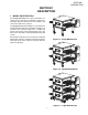
SECTION 1 DESCRIPTION SECTION 1 DESCRIPTION I. MODEL IDENTIFICATION The Blodgett BE3240-Series may be used either as a single oven or stacked for use as double or triple ovens. The major difference between the oven models in this series is the width of the conveyor. A single BE3240-Series Oven (Figure 1-1) is mounted on a base pad with legs and casters. A double oven (Figure 1-2) consists of two, stacked, single ovens. A triple oven (Figure 1-3) consists of three stacked single ovens.
SECTION 1 DESCRIPTION 2
SECTION 1 DESCRIPTION II. PRINCIPLE OF AIR FLOW The fan-style blower draws air into the oven plenum where it is heated. The blower then pushes the hot air through the air fingers into the baking chamber. Each air finger contains an inner plate and outer plate that form the hot air into jets, distributing it across a conveyor belt on which the food product rides. Air is then pulled back into the blower and the process continues. The curving, black arrows of Figure 1-4 show this air flow. reflect more heat.
SECTION 1 DESCRIPTION II. PRINCIPLE OF AIR FLOW (Continued) B. Air Fingers Series ovens used to bake pizza have four bottom fingers and two top fingers. For special product baking requirements, a number of other styles of fingers and finger arrangements are available from the factory. The BE3240-Series Ovens are conveyorized ovens that employ vertical jets of hot air streaming from air fingers (Figure 1-5) to give uniform, intense heating.
SECTION 1 DESCRIPTION III. COMPONENT FUNCTION (Figure 1-6) Figure 1-6.
SECTION 1 DESCRIPTION III. COMPONENT FUNCTION A. Conveyor Motor and Conveyor Belt The conveyor belt is driven by a variable-speed electric motor (Figure 1-7) operating through a gear reducer. The motor speed is controlled by a digital control. The stainless-steel wire belt can travel in either direction at variable rates ranging from 3 minutes to 30 minutes; this is the time that a product can take to pass through the oven. B. Blower Fan The blower fan is located at the rear of the oven.
SECTION 1 DESCRIPTION Figure 1-8.
SECTION 1 DESCRIPTION F2. Blank Plates 1. Blank Plates- The Blank Plates are available to install on the plenum where an air finger is not required. Half Blank Plate Outer Plate Blank Plate Inner Plate Finger Manifold Assembly Baffle Figure 1-9. Blank Plates (two sizes) and an Air Finger.
SECTION 2 INSTALLATION SECTION 2 INSTALLATION NOTE: The oven, when installed, must be electrically grounded in accordance with local codes, or in the absence of local codes, with the National Electrical Code (NEC), or ANSI/NFPA70. I. UNLOADING Your Blodgett BE3240-Series Oven is shipped partially assembled. It will arrive in a carton on a crate. Carton size for a BE3240-Series Oven is: NOTE 84″ (2134mm) Long × There must be adequate clearance between the oven and any adjacent combustible construction.
SECTION 2 INSTALLATION BE3240 OVEN INSTALLATION REQUIRED KITS AND EQUIPMENT TYPE OF INSTALLATION BE3240 Gas Oven Installation Kit P/N 50663 BE3240 Single Oven Option Base w/15″ Legs, Casters & Top Kit P/N 34832 BE3240 Single Gas Oven 1 1 BE3240 Double Gas Oven 2 BE3240 Triple Gas Oven 3 BE3240 Double Oven Option Base w/6″ Legs, Casters & Top Kit P/N 34833 BE3240 Double Oven Option Base w/Casters & Top Kit P/N 34831 1 1 BE3240 Triple Oven Option Base w/Casters & Top Kit P/N 51139 1 PARTS LIST
SECTION 2 INSTALLATION Figure 2-2. Model BE3240 Single Oven Option Base with Legs and Top PARTS LIST FOR BE3240 SERIES SINGLE OVEN OPTION - BASE w/15² LEGS & TOP P/N 34832 ITEM NO. 1 2 3 4 5 6 7 8 9 10 QTY 1 4 2 2 32 32 32 4 1 1 PART NO.
SECTION 2 INSTALLATION Figure 2-3. Model BE3240 Double Oven Option Base with Legs and Top PARTS LIST FOR BE3240 SERIES DOUBLE OVEN OPTION - BASE w/6″″ LEGS, CASTERS & TOP P/N 34833 ITEM NO. 1 2 3 4 5 6 7 8 9 10 QTY 1 4 2 2 32 32 32 4 1 1 PART NO.
SECTION 2 INSTALLATION Figure 2-4. Model BE3240 Double Oven Option Base with Casters and Top PARTS LIST FOR BE3240 SERIES DOUBLE OVEN OPTION - BASE w/CASTERS & TOP P/N 34831 ITEM NO. 1 2 3 4 5 6 7 8 9 QTY 1 2 2 32 32 32 4 1 1 PART NO.
SECTION 2 INSTALLATION Figure 2-5. Model BE3240 Triple Oven Option Base with Outriggers and Top PARTS LIST FOR BE3240 SERIES TRIPLE OVEN OPTION - BASE w/CASTERS & TOP P/N 51139 ITEM NO. 1 2 3 4 5 6 7 8 9 10 11 12 13 14 15 16 QTY 1 4 2 2 4 4 32 32 32 16 8 8 8 4 1 1 PART NO.
SECTION 2 INSTALLATION 2 2 2 1 Conduit for Electrical Connections 2 RECOMMENDED MINIMUM CLEARANCES: Rear of Oven to Wall - 6″ (150mm) Non-control End of Oven to Wall - 0″ Control End of Oven to Wall - 0″ 1 Figure 2-6.
SECTION 2 INSTALLATION 1 Conduit for Electrical Connections 2 RECOMMENDED MINIMUM CLEARANCES: Rear of Oven to Wall - 6″ (150mm) Non-control End of Oven to Wall - 0″ Control End of Oven to Wall - 0″ 2 2 2 1 Figure 2-7.
SECTION 2 INSTALLATION 2 2 1 Conduit for Electrical Connections 2 RECOMMENDED MINIMUM CLEARANCES: Rear of Oven to Wall - 6″ (150mm) Non-control End of Oven to Wall - 0″ Control End of Oven to Wall - 0″ 2 1 Figure 2-8. MODEL BE3240 TRIPLE OVEN DIMENSIONS RESTRAINT CABLE INSTALLATION Install the restraint cable assembly on the oven, as shown in Figure 2-9. Figure 2-9.
SECTION 2 INSTALLATION UTILITY ROUGH-IN DIMENSIONS AND POSITIONING FOR BE3240-SERIES OVENS 5 WARNING DO NOT USE CONDUIT OR GAS LINE FOR GROUND CONNECTION. ON 6 OFF 2 3 1 24" 610mm 2 CAUTION 6 IT IS REQUIRED THAT THE OVEN BE PLACED UNDER A VENTILATION HOOD FOR ADEQUATE AIR SUPPLY AND VENTILATION. ON 27" 686mm OFF 2 3 2 4 13-1/2" 343mm 24" 610mm ELECTRIC AND GAS SUPPLY TO BE PROVIDED BY CUSTOMER Suggested dimensions are shown; utility code requirements supersede any factors shown.
SECTION 2 INSTALLATION II. VENTILATION GUIDELINES VENTILATION HOOD A mechanically driven ventilation system is required for the BE3240 Series Blodgett conveyorized gas ovens. The minimum hood canopy dimensions are outlined below. The rate of air flow exhausted through the ventilation system is generally between 1400 and 2500 cu. ft./min. (40 and 70 m3/min), but may vary depending on the oven configuration and hood design.
SECTION 2 INSTALLATION factory-authorized installer can perform the initial startup of the oven. VENTILATION CAPTURE TEST It is recommended that a 30 second smoke candle test be performed on your ventilation hood system. Follow the steps below to complete the ventilation smoke test. Check the oven data plate (Figure 2-11) before making any electric supply connections. Electric supply connections must agree with data on the oven data plate.
SECTION 2 INSTALLATION V. CONVEYOR REAR STOP AND END STOP INSTALLATION Locate the conveyor rear stop and end stop in the installation kit. Install the rear stop and end stop at the exit end of the oven. See Figure 2-14. Figure 2-14.
SECTION 2 INSTALLATION NOTES 22
SECTION 3 OPERATION SECTION 3 OPERATION I. CONTROL FUNCTIONS Figure 3-1. BE3240-Series Oven Control Functions WARNING The burner cannot operate and gas cannot flow through the burner without electric power. Do NOT attempt to operate the oven during a power outage. WARNING A possibility of injury from rotating parts and electric shock exists in this oven. Never disassemble or clean the oven with the BLOWER switch or any other oven control turned “ON” or “I”.
SECTION 3 OPERATION An air pressure switch monitors the air flow from the blower, acting as a safety interlock for the burner. The burner cannot light, if the air switch does not sense air flow off the main blower fan. II. COMPONENT INFORMATION AND LOCATION (Figures 3-1 and 3-2) A. Door Safety Switch The Door Safety Switch is located at the lower left side of control panel opening. Opening the control panel door permits this switch to open, disconnecting power to all electrical controls.
SECTION 3 OPERATION D. Conveyor The on-off switch for the conveyor motor is on the control panel. Also on the control panel is the digital conveyor speed control. The digital control can be adjusted from 3 min. to 30 min. bake time (conveyor speed). Refer to Figure 3-3. Conveyor speed is measured by the amount of time it takes for an item to go through the bake chamber of the oven. MEASURING CONVEYOR SPEED. See Figures 3-4 and 3-5. Figure 3-3.
SECTION 3 OPERATION 4. Set the temperature controller to the desired baking temperature. See section on bake times to determine desired temperature. WARNING OVEN MUST BE KEPT CLEAR OF COMBUSTIBLES AT ALL TIMES. NOTE: For complete temperature controller operation instructions refer to Step C. III. STEP-BY-STEP OPERATION 6. Close front window. Control Panel (On split belt ovens, two conveyor speed controls are mounted on the control panel.) A. Startup Procedures 7.
SECTION 3 OPERATION Figure 3-6.
SECTION 3 OPERATION II. NORMAL OPERATION - STEP-BY-STEP A.Daily Startup Procedure 7. 1. 2. 3. 4. 5. Check that the circuit breaker/fused disconnect is in the on position. Check that the window is closed. Turn the "CONVEYOR" ( ) switch to the “ON” ("I") position. Adjust the temperature controller to a desired set temperature, if necessary. • • 6. perature ( ) key to show the Actual Temperature in the display, and wait for the "ACTUAL TEMP" light to turn on.
SECTION 3 OPERATION "HEAT ON" Light Display Shows the Set Point or the Actual Temperature in degrees Fahrenheit (F) or Celsius (C). Lights when the burner is in operation. "SP LOCK" Light Lights when the set point is locked out from changes. This setting can only be changed by service personnel. "SET PT" (setpoint) Light Lights when the set point is shown in the display. OVERTEMP Light "ACTUAL TEMP" Light Lights when the oven temperature is greater than 650°F (343°C).
SECTION 3 OPERATION IV. QUICK REFERENCE: TROUBLESHOOTING SYMPTOM PROBLEM SOLUTION The oven temperature exceeded 650°F (343°C), and the burner was automatically shut down. • Follow the procedures under Daily Shutdown Procedures in this section to shut down the oven. Contact your Middleby Marshall Authorized Service Agent to determine and correct the cause of the condition to prevent damage to the oven.
SECTION 4 MAINTENANCE SECTION 4 MAINTENANCE WARNING Possibility of injury from rotating parts and electrical shock exist in this oven. Turn off and lockout or tagout electrical supply to oven(s) before attempting to disassemble, clean or service oven(s). Never disassemble or clean the oven with the blower switch or any other part of the oven turned on. WARNING Before performing any maintenance work or cleaning, turn main power switch off.
SECTION 4 MAINTENANCE I. MAINTENANCE - DAILY D. Crumb Pans (Figure 4-2) A. Exterior Remove and clean the crumb pan at each end of the oven. Each crumb pan can be removed by sliding it out, as shown in Figure 4-2. Reinstall the crumb pans after cleaning. Everyday you should clean the outside of the oven with a soft cloth and mild detergent. E. Window WARNING The window can be cleaned daily while it is in place. Never use a water hose or pressurized steam cleaning equipment when cleaning the oven.
SECTION 4 MAINTENANCE deposits use a non-caustic cleaner that will not react with the aluminized finger manifold surfaces. II. MAINTENANCE - MONTHLY NOTE: The oven interior may require cleaning more than once a month depending on the volume of baking. To clean the interior, you have to disassemble some parts of the oven.
SECTION 4 MAINTENANCE 4. Remove conveyor drive chain cover as shown. 5. Remove tension from drive chain by lifting and pushing the conveyor slightly into the oven. Remove drive chain from conveyor drive sprocket as shown. NOTE: The split belt conveyor assembly can only be removed from the drive end of the oven. 6. Begin sliding conveyor out of the oven as shown. Figure 4-4. Figure 4-7. 7. Continue sliding the conveyor completely out of the oven, fold it in half and then place it to the side for cleaning.
SECTION 4 MAINTENANCE B. Air Fingers Disassembly For Cleaning 1. As the air fingers are removed use a felt pen to mark all parts of the fingers. This includes the finger manifold, inner plate and the outer plate (refer to Figure 1-9). If a blank or choke plate is used, mark that plate also. Fingers are marked in the order shown; as viewed from the front of the oven. (The marks for an upper oven should be preceded with a “U”, example UB1, UT2, etc.) T1 T2 T3 T4 B1 B2 B3 B4 Standard Fingers 2.
SECTION 4 MAINTENANCE 6. To remove the inner plate, pull the plate out and then up. C. Reassembly of Air Fingers 1. Air fingers are made up of one inner plate, one outer plate and the finger housing manifold. Be sure to match up the markings (T1, T2, T3, etc.) on all the parts of the air fingers as you are reassembling. Figure 4-12. 7. The outer finger plate is stainless and may be cleaned by either soaking in a hot, strong detergent solution or using a caustic cleaner.
SECTION 4 MAINTENANCE 4. Replace the air fingers by pushing in at the back side. Remember to replace them according to the numbers marked on them when they were removed. They must go back in the same way they came out. IMPORTANT: Only M6 Fingers fit in the bottom row. All M3 and M1 finger cover plates have extended lips at front. This extended lip will not allow these fingers to be installed in the bottom row.
SECTION 4 MAINTENANCE 5. Install fingers and blank plates correctly with edges interlocked and no space between edges. Incorrect - Too Much Space Top Finger Blank Plate Tab on Outer Plate of Finger Located in Groove Incorrect - Too Much Space Top Finger Blank Plate Tab on Outer Plate of Finger Located in Groove Correct Edges Overlap Completely Top Finger Blank Plate Tab on Outer Plate of Finger Located in Groove Figure 4-19.
SECTION 4 MAINTENANCE D. Reinstall End Plugs 1. Reinstall lower end plug. Be sure to tighten two wing screws on the end plug. 2. Reinstall conveyor. 3. Reinstall upper end plug. Be sure to tighten two wing screws on the end plug. Figure 4-20. Figure 4-21.
SECTION 4 MAINTENANCE E. Conveyor Reassembly Into Oven F. Checking Conveyor Belt Tension 1. Lift conveyor and position it in oven as shown. WARNING NOTE: Conveyor assembly may be inserted into either end of oven. If it is to be installed from the non-drive end of the oven the drive sprocket assembly must be removed as shown in conveyor disassembly section. Oven conveyor belt must be cool when adjusting belt. Do not adjust belt if HOT. 1.
SECTION 4 MAINTENANCE G. Conveyor Belt Link Removal 4. Unhook the link to be removed. 1. Using long nose pliers, an entire link can be removed with the conveyor assembly either in or out of the oven. Position master links at end of conveyor as shown in Figure 4-25. 5. Pull up on the belt link section and remove. Do not discard the link removed as it may be used for making spare master links. NOTE: If a section of the conveyor belt is being replaced it should be done now.
SECTION 4 MAINTENANCE 6. Reconnect the inside master links (Figure 4-30.) H. Replacing Conveyor Belt If a section of the conveyor belt needs replacing it can be done with the conveyor assembly either in or out of the oven. The section of the conveyor belt furnished with the oven in the installation kit may then be used to replace a section. Follow the preceding procedure “H. Conveyor belt link removal” which outlines the disassembly procedure. I. Attaching Drive Chain 1.
SECTION 4 MAINTENANCE 4. Reassemble conveyor drive chain cover and then reassemble the bottom cover to the drive chain cover. III. MAINTENANCE - EVERY 3 MONTHS Install both upper end plugs. WARNING Shut OFF all electrical power and lock/tag out the switch before attempting maintenance work. Shut OFF gas supply to oven. NOTE: It is recommended that the 3-month maintenance be performed by an authorized Middleby Marshall technician. A.
SECTION 4 MAINTENANCE B. Electrical Terminals CAUTION Open the control cabinet door by removing the three screws from the control cabinet door. Tighten all electrical control terminal screws including the electrical contactor terminal screws as shown in Figure 4-37. Overtightening the belt will cause premature bearing failure and possible vibration problems. A spare belt is located inside the control compartment on the rear wall. 3.
SECTION 4 MAINTENANCE E. Blower Fan Shaft Bearing Lubrication 3. Remove the conveyor adjustment bolts to allow the idler brackets to swing free. CAUTION Over-greasing damages the bearing seals and accelerates grease loss, which shortens bearing life. Wipe off any excess grease on and around the bearing. Reinstall the rear shroud to allow the oven to operate Grease the two (2) main blower fan shaft bearings (Figure 4-41), using a special grease (MM P/N 17110-0015 lithiumbase, high-temperature grease).
SECTION 4 MAINTENANCE 6. Make sure bronze washer is in between the two halves. 9. Loosen the split locking collar. Figure 4-45. 7. Place the idler shaft assembly back into place and reinstall the adjustment screws. Figure 4-48. 10. Remove drive shafts by sliding to right then lifting the left side. Follow cleaning and lubricating procedures outlined in Steps 4-6. Figure 4-46. Figure 4-49. 8. Loosen the set screw on each conveyor drive sprocket and remove sprockets. 11.
SECTION 4 MAINTENANCE 12. Slide shaft assembly to right side, holding assembly in place. Slide split locking collar to the left side and tighten. 13. Slide rear conveyor drive sprocket onto shaft. Tighten the set screw of this drive sprocket until it extends into the hole of the hollow shaft. It should NOT touch the inner, solid shaft. Check to see that only the rear shaft moves when the sprocket is turned. If both shafts move, you have tightened the set screw too tight.
SECTION 4 MAINTENANCE KEY SPARE PARTS KIT can reduce serious downtime and loss of production, if a failure occurs. An oven can be purchased with a Key Spare Parts Kit (Figure 4-56). (The kit can be purchased when the oven is ordered, or later, from a Blodgett Authorized Parts Distributor). The kit contains many of the crucial parts that Replacement parts for this kit can be purchased from your Blodgett Authorized Parts Distributor.
SECTION 5 TROUBLESHOOTING SECTION 5 TROUBLESHOOTING PROBLEM: OVEN BLOWER AND CONVEYOR OPERATE, YET THE OVEN IS NOT HEATING PROBLEM: PRODUCTS ARE OVERCOOKED OR UNDERCOOKED Check for correct setting of conveyor speed control. Check for correct setting on temperature controller. Reset the temperature controller to a new setting (above 200°F), after turning the BLOWER/HEAT switch to off for 30 seconds. Set the conveyor speed control at correct setting. Turn temperature control to correct setting.
SECTION 5 TROUBLESHOOTING NOTES 50
SECTION 6 PARTS LIST ENGLISH SECTION 6 - PARTS LIST 51
SECTION 6 PARTS LIST ENGLISH 52
1 1 16 8 8 8 4 4 4 21 22 23 24 25 26 27 28 4 13 20 4 12 1 1 11 19 1 10 A/R 4 9 18 1 8 A/R 2 7 17 1 6 A/R 16 5 16 8 4 2 8 3 15 2 2 2 2 1 14 QTY.
SECTION 6 PARTS LIST ENGLISH 54
1 1 7 7A 57423 57603 LABEL, CTRL DOOR RT UPR BE3240 LABEL, CTRL DOOR RT LWR BE3240 CONTROL PANEL ENGLISH SECTION 6 PARTS LIST 55
SECTION 6 PARTS LIST ENGLISH 56
BLOWER AND SHROUD ENGLISH SECTION 6 PARTS LIST 57
SECTION 6 PARTS LIST ENGLISH 58
2 4 1 1 1 15 16 17 18 1 9 14 4 8 1 1 7 13 1 6 1 1 5 12 1 4 1 1 3 11 1 2 1 1 1 10 QTY.
SECTION 6 PARTS LIST ENGLISH 60
1 2 4 16 1 1 2 15 16 17 18 19 20 2 9 14 4 8 1 1 7 13 1 6 1 1 5 12 1 4 1 1 3 11 1 2 1 1 1 10 QTY.
SECTION 6 PARTS LIST ENGLISH 62
QTY. 1 1 1 1 1 8 8 8 4 4 4 4 1 1 1 ITEM 1 2 3 4 5 6 7 8 9 10 11 12 13 14 63 15 33812-3 31497 36451 A3682 21126-0004 3023A8807 A3896 21416-0001 21422-0001 1513D8805 50449 49953 44687 28021-0061 28021-0047 P/N THERMOCOUPLE, TYPE “J” SHIELDED 9.
SECTION 6 PARTS LIST NOTES ENGLISH 64
SECTION 7 ELECTRICAL SCHEMATICS Wiring Diagram, E208-240 50/60, 3PH 4W BE3240 SECTION 7 ELECTRICAL SCHEMATICS 65
Wiring Diagram, E380-480 50/60, 3PH 5W BE3240 SECTION 7 ELECTRICAL SCHEMATICS 66
Wiring Diagram, E380V 50/60, 3PH 5W BE3240 SECTION 7 ELECTRICAL SCHEMATICS 67
SECTION 7 ELECTRICAL SCHEMATICS NOTES 67
WARNING Improper installation, adjustment, alteration, service or maintenance can cause property damage, injury or death. Read the installation, operating and maintenance instructions thoroughly before installing or servicing this equipment. NOTICE During the warranty period, ALL parts replacement and servicing should be performed by your Blodgett Authorized Service Agent. Service that is performed by parties other than your Blodgett Authorized Service Agent may void your warranty.