IMPORTANT WARNING: IMPROPER INSTALLATION, ADJUSTMENT, ALTERATION, SERVICE OR MAINTENANCE CAN CAUSE PROPERTY DAMAGE, INJURY OR DEATH. READ THE INSTALLATION, OPERATING AND MAINTENANCE INSTRUCTIONS THOROUGHLY BEFORE INSTALLING OR SERVICING THIS EQUIPMENT FOR YOUR SAFETY Do not store or use gasoline or other flammable vapors or liquids in the vicinity of this or any other appliance. The information contained in this manual is important for the proper installation, use, and maintenance of this oven.
THE REPUTATION YOU CAN COUNT ON For over a century and a half, The Blodgett Oven Company has been building ovens and nothing but ovens. We’ve set the industry’s quality standard for all kinds of ovens for every foodservice operation regardless of size, application or budget. In fact, no one offers more models, sizes, and oven applications than Blodgett; gas and electric, full-size, half-size, countertop and deck, convection, Cook’n Hold, Combi-Ovens and the industry’s highest quality Pizza Oven line.
iv
TABLE OF CONTENTS TABLE OF CONTENTS (Continued) Page Page SECTION 1 DESCRIPTION .................................................................... 4 I. OVEN USES .................................................................... 4 II. OVEN COMPONENTS .................................................... 4 A. Window ....................................................................... 4 B. Conveyor End Stop ................................................... 4 C. Eyebrows ............................
NOTES vi
SECTION 1 - DESCRIPTION OVEN USES J. BG2136 ovens can be used to bake and/or cook a wide variety of food products, such as pizza, pizza-type products, cookies, sandwiches and others. Not Shown: II. OVEN COMPONENTS - see Figure 1-1. A. Window: Allows the user to see and access food products inside the baking chamber. B. Conveyor End Stop : Prevents food products from falling off the end of the moving conveyor. C. Eyebrows: Can be adjusted to various heights to prevent heat loss into the environment.
SECTION 1 - DESCRIPTION Table 1-3: Electrical specifications for gas ovens (per oven cavity) ENGLISH Main Blower Voltage Control Circuit Voltage 208/240V 120V conv. speed control & drive motor; all others as per line (208/240V) Phase Freq. Current Draw Poles Wires 1 Ph 50/60 Hz 6A * 2 Pole 3 Wire (2 hot, 1 gnd) * The current draw shown above is an average value for normal operation. The initial amperage draw on oven startup may exceed the listed value.
SECTION 2 - INSTALLATION • • • • Perform a gas leak test. Test for correct air supply. Test for proper combustion and gas supply. Check that the ventilation system is in operation. WARNING Keep the appliance area free and clear of combustibles. WARNING The oven must be installed on an even (level) non-flammable flooring and any adjacent walls must be non-flammable. Recommended minimum clearances are specified in the Description section of this Manual.
SECTION 2 - INSTALLATION Figure 2-1 - Installation Kit 2 3 1 ENGLISH 4a, 4b, 4c, 4d 8 12 16 14 13 15 6 11 5 10 7 9 I. INSTALLATION KIT - see Figure 2-1 Item 1 Qty. Single Oven 1 Qty. Double Oven 1 Qty. Triple Oven 1 Part No. 48605 Inc. with domestic ovens? Yes Inc.
3 1 GAS INLET 2 ELECTRICAL JUNCTION BOX 3 RECOMMENDED MINIMUM CLEARANCES: Rear of Oven to Wall - 6″ (150mm) Non-control End of Oven to Wall - 0″ Control End of Oven to Wall - 0″ 3 3 2 1 Figure 2-2. MODEL BG2136 SINGLE OVEN DIMENSIONS 1 GAS INLET 2 ELECTRICAL JUNCTION BOX 3 RECOMMENDED MINIMUM CLEARANCES: Rear of Oven to Wall - 6″ (150mm) Non-control End of Oven to Wall - 0″ Control End of Oven to Wall - 0″ 3 3 3 2 1 Figure 2-3.
SECTION 2 - INSTALLATION ENGLISH 3 3 3 1 GAS INLET 2 ELECTRICAL JUNCTION BOX 3 RECOMMENDED MINIMUM CLEARANCES: Rear of Oven to Wall - 6″ (150mm) Non-control End of Oven to Wall - 0″ Control End of Oven to Wall - 0″ 2 1 Figure 2-4.
SECTION 2 - INSTALLATION IMPORTANT Where national or local codes require the installation of fire suppression equipment or other supplementary equipment, DO NOT mount the equipment directly to the oven. MOUNTING SUCH EQUIPMENT ON THE OVEN MAY: • VOID AGENCY CERTIFICATIONS • RESTRICT SERVICE ACCESS • LEAD TO INCREASED SERVICE EXPENSES FOR THE OWNER A. Recommendations NOTE THAT THE HOOD DIMENSIONS SHOWN IN FIGURE 2-5 ARE RECOMMENDATIONS ONLY.
SECTION 2 - INSTALLATION III. ASSEMBLY Figure 2-6 - Leg extension and casters installation ENGLISH A. Top Panel and Base Pad Assembly 1. Install the four leg extensions onto the base pad using the 3/8"-16x1" screws, 3/8" flat washers, and 3/8" lockwashers supplied in the Base Pad Kit. See Figure 2-6. Check that the finished sides of each leg extension face OUTWARDS.
SECTION 2 - INSTALLATION B. Stacking Figure 2-8 - Stacking and Top panel installation For single ovens, skip ahead to Part C, Restraint Cable Installation. #10 x 2" screws Top panel • • ENGLISH IMPORTANT Blodgett STRONGLY RECOMMENDS that BG2136 oven cavities be stacked using the following: PS500 Series Stacking Lift Kit, P/N 30580 BG2136 Stacking Hardware Kit, P/N 46494 Contact your Blodgett Authorized Service Agent for complete stacking instructions. 1.
SECTION 2 - INSTALLATION ENGLISH D. Conveyor Installation 1. Unfold the conveyor as shown in Figure 2-10. Then, begin to slide the conveyor into the end of the oven. The conveyor can only be installed from the end of the oven with the drive motor. 2. Continue moving the conveyor into the oven until the frame protrudes equally from each end of the oven. Check that the crumb tray supports located on the underside of the conveyor frame rest firmly against the lower end plugs, as shown in Figure 2-11.
5. If it is necessary to add or remove conveyor links to achieve the correct tension, OR if it is necessary to reverse the conveyor belt for correct orientation, the belt will need to be removed from the conveyor frame. If this is necessary, perform the following procedure: E. Final Assembly 6. Install the drive chain between the conveyor drive sprocket and the motor sprocket. To install the chain, it will be necessary to lift the drive end of the conveyor slightly.
SECTION 2 - INSTALLATION IV. ELECTRICAL SUPPLY ENGLISH WARNING Authorized supplier personnel normally accomplish the connections for the ventilation system, electric supply, and gas supply, as arranged by the customer. Following these connections, the factory-authorized installer can perform the initial startup of the oven. The oven requires a ground connection to the oven ground screw located in the electrical junction box. (The box is shown in Figure 2-14.
NOTE: Certain safety code requirements exist for the installation of gas ovens; refer to the beginning of Section 2 for a list of the installation standards. In addition: • In the USA, the installation must conform with local codes, or in the absence of local codes, with the National Fuel Gas Code, ANSI Z223.1. • In Canada, the installation must conform with local codes, or in the absence of local codes, with the Natural Gas Installation Code, CAN/CGA-B 149.
SECTION 2 - INSTALLATION ENGLISH 1. Checking the Gas Supply (Inlet) Pressure a. With the main gas supply valve closed and the circuit breaker/fused disconnect in the OFF ("O") position, open the inlet pressure tap shown in Figure 2-17 and attach a manometer to the tap. b. Depress the safety switches to allow the oven to operate. c. Open the main gas supply valve. Switch the circuit breaker/ fused disconnect to the ON ("I") position. d.
ENGLISH SECTION 3 - OPERATION D C B A I. A. B. LOCATION AND DESCRIPTION OF CONTROLS "BLOWER/HEAT" Switch: Turns the blower and cooling fans on and off, as well as, the gas burner system. The gas burners will activate shortly after the BLOWER/HEAT switch is turned on. The Temperature of the oven will be regulated by the temperature controller. D. Digital Temperature Controller: Continuously monitors the oven temperature.
SECTION 3 - OPERATION II. NORMAL OPERATION - STEP-BY-STEP ENGLISH A. DAILY STARTUP PROCEDURE 8. Allow the oven to preheat for 10 minutes after it has reached the set point temperature. 1. Check that the circuit breaker/fused disconnect is in the on position. Check that the window is closed. B. DAILY SHUTDOWN PROCEDURE 1. Turn the "BLOWER"/ "HEAT" ( )( ) switch to the "OFF" ("O") position. Note that the blowers will remain in operation until the oven has cooled to below 200°F (93°C). 2.
SECTION 3 - OPERATION ENGLISH III. QUICK REFERENCE: DIGITAL TEMPERATURE CONTROLLER "HEAT ON" Light Display Shows the Set Point or the Actual Temperature in degrees Fahrenheit (F) or Celsius (C). Lights when the burner is in operation. "SP LOCK" Light Lights when the set point is locked out from changes. This setting can only be changed by service personnel. "SET PT" (setpoint) Light Lights when the set point is shown in the display.
SECTION 3 - OPERATION NOTES ENGLISH 18
SECTION 4 - MAINTENANCE WARNING 1. 2. 3. 4. Switch off the oven and allow it to cool. Do NOT service the oven while it is warm. Turn the full-flow gas safety valve to the off position. Turn off the electric supply circuit breaker(s) and disconnect the electric supply to the oven. If it is necessary to move a gas oven for cleaning or servicing, disconnect the gas supply before moving the oven. When all cleaning and servicing is complete: 1.
SECTION 4 - MAINTENANCE Figure 4-2 - Removing Air Fingers and Plates II. MAINTENANCE - MONTHLY Check that the oven is cool and the power is disconnected, as described in the warning at the beginning of this Section. B. Refer to Part D, Conveyor Installation, in the Installation section of this Manual. Then, remove the following components from the oven: • Conveyor end stop • Crumb trays • Chain cover • Drive chain • End plugs • Conveyor assembly ENGLISH A. C.
SECTION 4 - MAINTENANCE Remove the master links from each conveyor belt. Then, roll the belts up along the length of the conveyor to remove them from the frame. 3. Remove the two conveyor adjustment screws from the idler end of the conveyor frame, as shown in Figure 44. 4. Remove the idler shaft assembly from the conveyor. 5. Pull apart the two sections of the idler shaft. 6. Clean the shafts thoroughly using a rag.
Blower Belt 1. Remove the six screws shown in Figure 4-7. Then, remove the rear panel from the oven. 2. Check the blower belt for the proper 1/4" (6mm) deflection at the center, and for cracking or excessive wear. See Figure 4-7. Overtightening the belt will cause premature bearing failure and possible vibrations. A loose belt may also cause vibrations. 3. If necessary, adjust the tension of the belt by loosening the four motor mounting bolts.
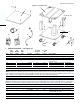
SECTION 5 - PARTS LIST SECTION 5 - PARTS LIST 4 2 5 3 7 6 ENGLISH 1 8 13 9 10 12 11 16 15 14 17 I. KEY SPARE PARTS KIT ITEM QTY. P/N DESCRIPTION 1 1 47321 DIGITAL TEMPERATURE CONTROLLER 2 1 51067 CONVEYOR DRIVE MOTOR W/PICKUP ASSY.
ENGLISH 24
1 1 1 15 16 31 8 14 1 7 1 2 6 13 2 5 1 -- 4d 12 -- 4c 1 -- 4b 11 4 4a 32 1 3 10 2 2 32 1 1 9 QTY. SINGLE OVEN ITEM 25 2 1 1 1 2 1 32 32 31 1 2 2 -- 4 4 4 1 4 1 QTY. DOUBLE OVEN 3 -- 1 1 3 1 32 32 31 1 2 2 4 -- -- -- 1 4 1 QTY.
page 1 ENGLISH seite 29 DEUTSCH page 57 FRANÇAIS página 85 ESPAÑOL 26
2 1 1 1 1 1 1 1 1 1 1 1 1 1 8 8 2 2 2 1 2 3 4 5 6 7 8 9 10 11 12 13 14 15 16 17 18 19 ITEM QTY.
page 1 ENGLISH seite 29 DEUTSCH page 57 FRANÇAIS página 85 ESPAÑOL 28
1 1 2 1 1 1 1 1 17 18 19 20 21 22 23 2 11 16 1 10 1 1 9 15 1 8 1 1 7 14a 1 6a 1 1 6 14 1 5 1 1 4 13 2 3 1 2 2 12 1 1 ITEM QTY.
page 1 ENGLISH seite 29 DEUTSCH page 57 FRANÇAIS página 85 ESPAÑOL 30
1 2 14 15 2 9 2 1 8 13 1 7 A/R 1 6 12 1 5 1 1 4 11 1 3 1 1 2 10 1 1 ITEM QTY. 31 30002 49940 44888 48740 41647 52291 23051-0003 50239 31651 41872 45644 28021-0047 32108 44390 27470-0004 P/N TAP PLUG MANIFOLD 1 23 1 FRANÇAIS page 57 1 1 página 85 -- -- NOT SHOWN: 26 1 3 22 25 1 21 1 1 20 24 1 1 1 3 3 19 18 17 16b 16a ITEM QTY. ESPAÑOL COMPRESSION FITTING, 1/4" TUBE TUBE, ALUMINUM, 1/4" (6.35mm) O.D.
page 1 ENGLISH seite 29 DEUTSCH page 57 FRANÇAIS página 85 ESPAÑOL 32
2 1 1 2 2 2 2 2 1 1 1 1 2a 2b 3 4 5 6 7 8 9 10 ITEM QTY. 33 44688 44687 44748 50151 50160 22072-0025 35121-0045 42999 42753 42752 42951 P/N FRANÇAIS page 57 1 1 1 1 1 1 página 85 20 19 18 17 16 15 1 4 13 14 4 4 12 11 ITEM QTY.
page 1 ENGLISH seite 29 DEUTSCH page 57 FRANÇAIS página 85 ESPAÑOL 34
1 4 2 2 2 2 2 16 17 18 19 20 21 1 10 15 1 9 1 2 8 14 2 7 1 2 6 13 2 5 2 4 4 12 1 3 4 1 2 11 1 1 ITEM QTY.
page 1 ENGLISH seite 29 DEUTSCH page 57 FRANÇAIS página 85 ESPAÑOL 36
48847 1 1 1 1 1 4 2 2 2 2 1 1 1 1 1 4 2 2 2 2 1 2 3 4 5 6 7 8 9 10 11 37 12 13 14 15 16 17 18 19 20 35000-1008 <---- 37000-0413 <---- <---- <---- <---- <---- 48769 48746 <---- <---- <---- <---- <---- <---- <---- <---- <---- P/N - 60" CONVEYOR ITEM QTY.
NOTES page 1 ENGLISH seite 29 DEUTSCH page 57 FRANÇAIS página 85 ESPAÑOL 38
SECTION 6 - ELECTRICAL WIRING DIAGRAMS SECTION 6 - ELECTRICAL WIRING DIAGRAMS IMPORTANT An electrical wiring diagram for the oven is also located inside the machinery compartment. 39 page 1 page 57 página 85 seite 29 FRANÇAIS ESPAÑOL DEUTSCH ENGLISH Fig.
NOTES
NOTES
WARNING Improper installation, adjustment, alteration, service or maintenance can cause property damage, injury or death. Read the installation, operating and maintenance instructions thoroughly before installing or servicing this equipment. NOTICE During the warranty period, ALL parts replacement and servicing should be performed by your Blodgett Authorized Service Agent. Service that is performed by parties other than your Blodgett Authorized Service Agent may void your warranty.