
BCT and BLCT Series Combi Ovens Manual


7
Installation
Oven Location and Leveling
The well planned and proper placement of your oven will
result in long term operator convenience and satisfactory
performance.
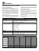
Certain minimum clearances must be maintained be-
tween the oven and any combustible or non-combustible
construction.
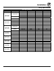
MINIMUM REQUIRED CLEARANCES
Size Left Right Back
Electric Ovens
61, 101,
102 & 202
2.75”
(70mm)
2.75”
(70mm)
2”
(50mm)
62 0”
(0mm)
4”
(102mm)
2”
(50mm)
Gas Ovens
61, 101,
102 & 202
2.75”
(70mm)
2.75”
(70mm)
2”
(50mm)
62 0”
(0mm)
4”
(102mm)
2”
(50mm)
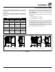
Strong sources of heat such as hotplates, tilting frying
pans, deep fat fryers, etc. should not be placed near the
oven, especially near its right side. An optional side heat
shield is available.
In addition, the following clearances are recommended
for servicing.
• Oven body sides - 12” (30cm)
• Oven body back - 12” (30cm)
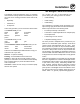
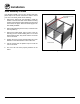
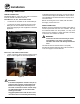
To ensure that the oven functions correctly when installed,
it should be placed upright and level (horizontally). This is
measured at the front and side edge of the roof. The oven
can be levelled using the adjusting screws on the stand or
on the legs of table models. The height of the oven should
also be adjusted to t the trolley for rack.
Correct Installation Incorrect Installation
Figure 2