BLT/BLP-G Series KTT-E Series ELECTRIC GAS TABLE TOP TILTING BRAISING PAN KETTLE INSTALLATION INSTALLATION–- OPERATION OPERATION – - MAINTENANCE BLODGETT OVEN COMPANY BLODGETT OVEN COMPANY www.blodgett.com www.blodgett.
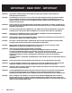
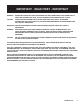
IMPORTANT - READ FIRST - IMPORTANT WARNING: DISCONNECT POWER BEFORE SERVICING. FAILURE TO DISCONNECT COULD RESULT IN ELECTROCUTION AND DEATH. CAUTION: UNIT WEIGHS 470 TO 560 LB. (191 TO 255 KG). FOR SAFE HANDLING, INSTALLER SHOULD OBTAIN HELP AS NEEDED, OR EMPLOY APPROPRIATE MATERIALS HANDLING EQUIPMENT (SUCH AS A FORKLIFT, DOLLY, OR PALLET JACK) TO REMOVE THE UNIT FROM THE SKID AND MOVE IT TO THE PLACE OF INSTALLATION.
IMPORTANT - READ FIRST - IMPORTANT WARNING: BEFORE REPLACING ANY PARTS, DISCONNECT THE UNIT FROM THE ELECTRIC POWER SUPPLY AND CLOSE THE MAIN GAS COCK. ALLOW FIVE MINUTES FOR UNBURNED GAS TO VENT. CAUTION: USE OF ANY REPLACEMENT PARTS OTHER THAN THOSE SUPPLIED BY AUTHORIZED DISTRIBUTORS CAN CAUSE INJURY TO THE OPERATOR AND DAMAGE TO THE EQUIPMENT AND WILL VOID ALL WARRANTIES. IMPORTANT: SERVICE PERFORMED BY OTHER THAN AUTHORIZED SERVICE AGENT WILL VOID ALL WARRANTIES.
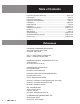
Table of Contents Important Operator Warnings ....................................................page 2-3 References.................................................................................... page 4 Equipment Description............................................................... page 5-6 Inspection and Unpacking ............................................................ page 7 Installation ..................................................................................
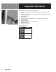
Equipment Description Blodgett BLT/BLP Tilting Braising Pans provide a stainless steel pan equipped with patented heat transfer fins, burner/combustion chamber, hand-operated or electric powered tilting mechanism, thermostatic controls, and hinged cover. The appliance serves as braising pan, griddle, fry pan, oven, kettle, bainmarie and food warmer/ server, can be adapted for use as a non-pressure steamer and can be used to stir-fry, reheat and saute foods.
Equipment Description Optional Tangent Draw-off Optional equipment available with these models are: 1. Fill faucet with swing spout. (Left or right mounted) - specify single or double pantry 2. Fill faucet with 48” or 60” spray hose assembly (left or right mounted) - specify single or double pantry 3. Caster mounting kit 4. Flanged Feet 5. 2” Tangent draw-off (Factory-installed must be indicated on initial order) 6. Steamer Insert set 7. Steamer Pan Carrier 8.
Inspection & Unpacking CAUTION SHIPPING STRAPS ARE UNDER TENSION AND CAN SNAP BACK WHEN CUT. The unit will arrive completely assembled, wrapped in protective plastic on a heavy skid, in a heavy cardboard carton. Immediately upon receipt, inspect the carton for damage. Report any apparent shipping damage or an incorrect shipment to the delivery agent. CAUTION UNIT WEIGHS 420 TO 560 LB (190 TO 255 KG).
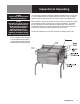
Installation CAUTION INSTALLER MUST VERIFY THAT THE INSTALLATION COMPLIES WITH THE APPLICABLE LOCAL CODES AND REGULATIONS. THE UNIT MUST BE INSTALLED BY A LICENSED PLUMBER OR GAS FITTER WHEN INSTALLED WITHIN THE COMMONWEALTH OF MASSACHUSETTS. Install the braising pan in a well ventilated room for efficient performance. Remove any items which might obstruct or restrict the flow of air for combustion and ventilation. Clear all combustible material from the area directly around the unit. 1.
Installation 9. Adequate space for proper service and operation is required. DO NOT block any air intake spacings to the combustion chamber or obstruct air flow. 10. After the pan has been connected to the gas supply, check all gas joints for leaks. A soap solution or other suitable leak detector should be used. Do not use flame to check for leaks. 11. PRESSURE TEST WARNING a. Test pressure exceeding 0.5 PSIG (3.45kPa). During pressure testing of the gas supply piping system at pressures exceeding 0.
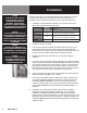
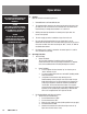
Operation WARNING KEEP THE AREA AROUND BRAISING PAN FREE AND CLEAR OF COMBUSTIBLE MATERIALS. A. CAUTION KEEP FLOORS IN BRAISING PAN WORK AREA CLEAN AND DRY. IF SPILLS OCCUR, CLEAN IMMEDIATELY TO AVOID THE DANGER OF SLIPS OR FALLS. CAUTION REPLACE THE HOLE PLUG BEFORE CLEANING OTHERWISE WATER COULD ENTER THE ELECTRICAL CONTROL BOX AND DAMAGE THE PARTS. B. Tilting pan body Controls Operator controls for the braising pans are: 1. Power ON Switch and Power ON indicator 2.
Operation CAUTION DO NOT HEAT AN EMPTY PAN FOR MORE THAN FIVE MINUTES AT A SETTING HIGHER THAN 300°F. DAMAGE TO THE PAN COULD RESULT. CAUTION KEEP FLOORS IN BRAISING PAN WORK AREA CLEAN AND DRY. IF SPILLS OCCUR, CLEAN IMMEDIATELY TO AVOID THE DANGER OF SLIPS OR FALLS. CAUTION REPLACE THE HOLE PLUG BEFORE CLEANING OTHERWISE WATER COULD ENTER THE ELECTRICAL CONTROL BOX AND DAMAGE THE PARTS. 3. b. To Turn Off Pan 1. Set the thermostat to “OFF”. 2. Set Power Switch to “OFF.” 3.
Operation WARNING WHEN TILTING BRAISING PAN FOR PRODUCT TRANSFER: 4. 1) USE CONTAINERS DEEP ENOUGH TO CONTAIN AND MINIMIZE PRODUCT SPLASHING. Disconnect the cable from its anchor point on the floor or wall. Anchor the unit again as soon as it is in its new operating location or returned to the previous location. Turn on the gas supply and check for leaks with a soap solution. If leaks are found, do not operate the equipment. Call for service.
Sequence of Operation The following “action-reaction” outline is provided to help understand how the kettle works. A. B. Standard Models with Spark Ignition 1. When the power switch is turned on, it starts the spark igniter and opens the automatic valve for the pilot burner. The spark ignites a pilot flame, which heats the sensor. The sensor then sends a signal to turn off the spark. The flame thereafter acts as a standing pilot until the power is turned off. 2.
Sequence of Operation C. All Models 1. The thermostat controls heating by alternately calling for flames at the full capacity of the main burners and then signaling the control to shut the burner off completely. Because the control works in this “all or nothing” way, the pan heats as fast as it can until it reaches the set temperature.
Cleaning WARNING KEEP WATER AND SOLUTIONS OUT OF CONTROLS AND ELECTRICAL EQUIPMENT. DO NOT USE A HIGH PRESSURE HOSE TO CLEAN THE CONTROL CONSOLE, ELECTRICAL CONNECTIONS, ETC. CAUTION MOST CLEANERS ARE HARMFUL TO THE SKIN, EYES, MUCOUS MEMBRANES AND CLOTHING. PRECAUTIONS SHOULD BE TAKEN TO WEAR RUBBER GLOVES, GOGGLES OR FACE SHIELD AND PROTECTIVE CLOTHING. CAREFULLY READ THE WARNINGS AND FOLLOW THE DIRECTIONS ON THE LABEL OF THE CLEANER TO BE USED. 1.
Maintenance WARNING ELECTRIC POWER ALWAYS SHOULD BE SHUT OFF BEFORE WORK IS DONE ON INTERNAL COMPONENTS. Your braising pan is designed to require minimum maintenance, but certain parts may need replacement after prolonged use. After installation, no user adjustment should be necessary. If a service need arises, only authorized personnel should perform the work. WARNING DISCONNECT ELECTRICAL POWER FROM THE UNIT BEFORE ATTEMPTING TO GREASE THE TRUNNION BEARINGS.
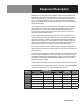
Troubleshooting Your braising pan will operate smoothly and efficiently if properly maintained. However, the following is a list of checks to make in the event of a problem. If the actions suggested do not solve the problem, call your qualified Service Representative. If an item on the list is followed by X, the work should only be performed by a qualified service representative. WARNING BEFORE REPLACING ANY PARTS, DISCONNECT THE UNIT FROM THE ELECTRICAL POWER SUPPLY AND CLOSE THE MAIN GAS VALVE.
Troubleshooting B. STANDARD MODELS WITH ELECTRONIC IGNITION SYSTEM (REFER TO SCHEMATIC) SYMPTOM WHO WHAT TO CHECK (X indicates work that should only be performed by a qualified service representative) System does not produce a spark. Authorized a. Thermostat, and close the contacts if they are open X Service Rep Only b. AC voltage between terminals on secondary side of transformer. If it is not 24 Volt, replace the transformer X c. That the high tension cable is in good condition.
Troubleshooting C. MODELS WITH STANDING PILOT IGNITION SYSTEM SYMPTOM WHO WHAT TO CHECK (X indicates work that should only be performed by a qualified service representative) Pilot will not light. User a. Lighting procedure, to ensure that the instructions in the Operation section of this manual are followed. Authorized b. That the pilot gas supply line is purged of air. X Service Rep Only c. Pilot gas adjustment screw, to ensure that it is open. X d. Pilot tubing and orifice for clogging.
Parts List Stand & Foot Assembly Key Description Part # 1 CASTER KIT (SET OF 2 WITH BRAKE AND 2 W/O BRAKE) 170810 1 CASTER WITH BRAKE (W/O FOOT ADAPTER) 146513 1 CASTER WITHOUT BRAKE (W/O FOOT ADAPTER) NOT SHOWN 146515 2 FOOT ADAPTER 146516 3 FLANGED FOOT (W/O FOOT ADAPTER) 146521 4 BULLET FOOT (W/O FOOT ADAPTER) 146628 5 FRICTION RING 146520 20 OM-BLT/BLP-G
Parts List Cover & Counterbalance Assemblies Key Qty Description Part # 1 1 COVER & COUNTERBALANCE ASSEMBLY, 30 GALLON - NO KNOB 158643 1 1 COVER & COUNTERBALANCE ASSEMBLY, 40 GALLON - NO KNOB 158658 3 4 STUD WELD, 1/4”-20 X 1-1/4” 012589 4 4 WASHER, LOCK 3/8” 005618 5 4 SCREW, HEX HEAD CAP 3/8”-16 X 1” 005612 6 4 NUT, HEX 3/8”-16 005619 7 4 DOME NUTS, 1/4-20 090567 8 2 SCREW, TRUSS HEAD, #10-32 X 3/8” 004173 9 1 VENT COVER ASSY.
Parts List Gas Piping Assemblies Key Qty Description Part # 1 2 1 5 U BOLT 3/4 PIPE WASHER PLAIN 1/4 N87786 005472 3 5 NUT HEXAGON KEPS 1/4-20 WITH 012940 ELBOW 90 DEG 1/2 NPT NIPPLE 1/2 NPT X 11 IGNITION MODULE PLATE ASSY ELECTRONIC IGNITION 008747 005673 4 5 1 1 6 1 6 1 7 1 SWIVEL JOINT 1/2 NPT (GAS) 076680 8 9 10 11 12 2 1 1 1 1 UNION ELBOW TEE 1/2 NPT NIPPLE 1/2 NPT X 3.
Parts List Combustion Chamber & Gas Manifold Assemblies Key Qty Description Part # 1 1 COMBUSTION CHAMBER ASSY, 30 GAL. 145941 1 1 COMBUSTION CHAMBER ASSY, 40 GAL. 144843 MANIFOLD, 30 GAL. MANIFOLD, 40 GAL.
Parts List Electrical Control Components - Gas 24 OM-BLT/BLP-G
Parts List Electrical Control Components - Gas Key Qty 1 2 3 4 5 6 7 8 9 10 11 12 13 14 15 16 17 18 19 20 21 22 23 24 25 26 27 28 29 30 32 33 34 35 36 37 38 39 40 40 40 41 42 43 43 43 43 1 1 1 3 4 1 1 1 1 1 1 2 2 2 1 1 1 6 1 1 1 3’ 2 6” 3 1 1 2 2 6 1 1 1 1 1 1 1 1 1 1 1 1 1 1 1 1 1 Description FUSE HOLDER MAIN CONTROLS-ELECTRONIC IGNITION ONLY FUSE -24VAC CONTROL, 3A, TYPE AG-ELECTRONIC IGNITION ONLY SCREW, ROUND HEAD #8-32 X 1-1/4”-ELECTRONIC IGNITION ONLY SCREW, ROUND HEAD #6-32 X 3/8” SCREW, HEX SLOTTE
Parts List Trunnion Cover 26 OM-BLT/BLP-G
Parts List Trunnion Cover Gas Part #s Key Qty Trunnion Cover Description Manual Tilt Electronic Ignition Power Tilt Electronic Ignition Manual Tilt Standing Pilot 1 1 THERMOSTAT BOX ASSEMBLY 146131 146131 146131 1a 4 WASHER LOCK 1/4 005655 005655 005655 1b 1 THERMOSTAT BOX SHELL 146132 146132 146132 1c 1 COVER, CONTROL CONSOLE SHELL 146147 146147 146147 1d 1 BRACKET, THERMOSTAT BOX 146130 146130 146130 1e 5 NUT DOME HIGH PROFILE - 1/4-20 090567 090567 090567 054306
Parts List Manual Tilt Assembly Key Qty Description Part # 1 1 GEAR CARRIER 002624 2 1 SHAFT, HANDWHEEL 144834 3 1 GEAR, WORM 128001 4 1 GEAR SECTOR 009829 5 1 KEY GIB 012031 6 1 HANDWHEEL 012061 7 2 PIN ROLL 012614 8 2 SCREW SET SOCKET 012060 9 2 BEARING ROLLER 002790 10 2 BEARING SLEEVE 137239 11 1 PLUG PIPE 010286 14 1 FITTING GREASE 90 (NOT SHOWN) 012195 15 1 BUSHING SNAP (NOT SHOWN) 000453 16 2 WASHER LOCK 005618 17 2 SCREW HEX HEAD CAP 0056
Parts List Power Tilt Components Gas-Electronic Ignition Key Qty 1 1 2 1 3 4 4a 4b 4c 4d 4e 5 6 6a 7 8 9 10 11a 11b 11c 1 1 1 2 2 1 1 1 1 2 1 1 1 1 1 1 1 11d 2 12 13 5 5 14 3 15 16 2 2 17 2 18 1 - 1 - 1 - 1 - 2 - 1 - 1 Description Part # ELECTRIC TILT SHAFT POWER LIFT MOTOR [115 VDC] SHAFT COUPLING GEAR CARRIER ASSY CARRIER GEAR BEARING ROLLER BEARING SLEEVE PLUG PIPE FITTING GREASE 90 GEAR, WORM GEAR SECTOR SCREW SET SOCKET KEY GIB PIN ROLL MOTOR BRACKET REAR MOTOR BRACKET F
Parts List Fuel Gas Conversion (For conversion of a natural gas unit to propane or a propane model to natural gas) BLT, BLP WITH ELECTRONIC IGNITION Qty Description 30GS, 40GS-BLT WITH STANDING PILOT Natural Gas Part # LP Gas Part # Qty Description Natural Gas Part # LP Gas Part # 1 PILOT ORIFICE 119449 098647 1 PILOT ORIFICE 137511 123689 % BURNER ORIFICE 128158 146148 % BURNER ORIFICE 128158 146148 1 IGNITION TUBE ORIFICE 40 GAL. 101665 101623 1 IGNITION TUBE ORIFICE 40 GAL.
Schematics Electronic Ignition System Manual Tilt OM-BLT/BLP-G 31
Schematics Electronic Ignition System Power Tilt 32 OM-BLT/BLP-G
Diagrams & Schematics Standing Pilot Ignition System OM-BLT/BLP-G 33
Service Log Model No: Purchased From: Serial No: Location: Date Purchased: Date Installed: Purchase Order No: For Service Call: Date 34 OM-BLT/BLP-G Maintenance Performed Performed By
Service Log Model No: Purchased From: Serial No: Location: Date Purchased: Date Installed: Purchase Order No: For Service Call: Date Maintenance Performed Performed By OM-BLT/BLP-G 35
BLODGETT OVEN COMPANY www.blodgett.