COS-20G INSTALLATION AND OPERATION MANUAL FOR EXPORT SERIES GAS COMBINATION OVENS BLODGETT COMBI www.blodgett.
Table of Contents Introduction The Blodgett Combi-Oven/Steamer . . . . . . . . . . . . . . . . . . . . . . . . . . . . . . . . . Description of the Combi-Oven/Steamer . . . . . . . . . . . . . . . . . . . . . . . . . . . . Oven Features . . . . . . . . . . . . . . . . . . . . . . . . . . . . . . . . . . . . . . . . . . . . . . . . . . . 2 3 4 Installation Owner’s Responsibilities . . . . . . . . . . . . . . . . . . . . . . . . . . . . . . . . . . . . . . . . . . Location and Ventilation . . . . . . . . .
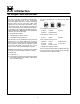
Introduction The Blodgett Combi-Oven/Steamer For easy operation you can choose from three modes: For quite some time, commercial cooking equipment has remained more or less unchanged. There are kettles, deck ovens, the good old range with its legion of pots and many other extra appliances. The result: time expenditure, excessive manual work, and countless cleaning processes. The last few years have paved the way for a revolution in the equipment of restaurant and institutional kitchens.
Introduction Description of the Combi-Oven/Steamer ABOUT THE OVEN/STEAMER OVEN/STEAMER OPERATION Blodgett Combi-Oven/Steamers are quality produced using high-grade stainless steel with first class workmanship. The practical oven door, with a viewing window, has a wide swing radius and handle which can be operated easily, even with wet or greasy hands.
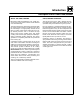
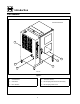
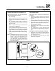
Introduction Oven Features Standard Features 4 2 3 5 1 6 COS-20G Figure 1 1 Control Panel 4 Vent (not shown) 2 Oven Door 5 Decalcifying Inlet & Funnel Assembly 3 Door Handle 6 Decalcifying Valve Lever 4
Installation Owner’s Responsibilities 1. Oven(s) are uncrated, stacked (if applies) and put in place. 2. The owner/operator must have the following utility requirements met and installed. NOTE: Refer to the Utility Connection information provided.
Installation Location and Ventilation LOCATION VENTILATION The well planned and proper placement of your appliance will result in long term operator convenience and satisfactory performance. The necessity for a properly designed and installed ventilation system cannot be over emphasized. The ventilation system will allow the unit to function properly while removing unwanted vapors and products of combustion from the operating area.
Installation Utility Connections NOTE: Utility connections must be performed by a qualified installer only. DRAIN CONNECTION A 5 cm copper pipe with standard drain pitch must be run to an open drain or connected to a standpipe equipped with a vent. WATER CONNECTION NOTE: Hot water maximizes steam production but is not required. Cold water may be supplied to both inlets if hot water is not available. NOTE: The waste water can also be directed to a nearby floor drain.
Installation Utility Connections ELECTRICAL CONNECTION GAS PIPING AND PRESSURE Before making any electrical connections to these units, check that the power supply is adequate for the voltage, amperage, and phase requirements stated on the rating name plate mounted on the appliance. A properly sized gas supply system is essential for maximum oven performance.
Installation Adjustments BEFORE SWITCHING THE APPLIANCE ON DOOR ADJUSTMENT Before applying power to the unit for the first time, check for the following conditions: The hinges may be adjusted using the following procedure: 1. Adjust the top hinge plate by loosening the three mounting bolts on the top right corner of the unit. 2. Adjust the bottom hinge pin by loosening the mounting bolt located under the bottom hinge plate on the lower right corner of the oven. 3.
Installation Final Check Lists NOTE: Final check list must be performed by a qualified installer only. ELECTRICAL CONTROL COMPARTMENT Applied voltage to unit voltage/phase suitable for appliance specified. j j j j j Remove side panel Set motor protector (F2) to on position Adjust motor protector to maximum Reset high limit thermostats F3 and F6 Reinstall side panel GAS FINAL CHECK j Verify inlet pressure is 20 mbar. Turn manual gas valve to on. Turn mode selector switch to STEAM.
Installation Final Check Lists OVEN OPERATIONAL TESTS NOTE: Checks to be made by customer or authorized service agent.
Operation Safety Information THE INFORMATION CONTAINED IN THIS SECTION IS PROVIDED FOR THE USE OF QUALIFIED OPERATING PERSONNEL. QUALIFIED OPERATING PERSONNEL ARE THOSE WHO HAVE CAREFULLY READ THE INFORMATION CONTAINED IN THIS MANUAL, ARE FAMILIAR WITH THE FUNCTIONS OF THE OVEN AND/OR HAVE HAD PREVIOUS EXPERIENCE WITH THE OPERATION OF THE EQUIPMENT DESCRIBED. ADHERENCE TO THE PROCEDURES RECOMMENDED HEREIN WILL ASSURE THE ACHIEVEMENT OF OPTIMUM PERFORMANCE AND LONG, TROUBLE-FREE SERVICE.
Operation Oven Start-Up INITIAL OVEN START-UP COMBI MODE (if applicable) 1. Turn the manual gas valve to ON. 1. Turn the mode selector switch to COMBI. 2. The combustion blower turns on. STEAM MODE (if applicable) 3. The green POWER indicator lamp on the front control panel lights. 1. Turn the mode selector switch to STEAM. 2. The combustion blower turns on. 3. The green POWER Indicator lamp on the front control panel lights. 4.
Operation Standard Controls CONTROLS IDENTIFICATION 1. LOW WATER FILL LIGHT --- during the fill cycle, this light remains on until the water in the steam generator is at the proper level and up to temperature. During normal operation the light should not be on. If the light comes on, check the water level in the steam generator. 2. DON’T STEAM LIGHT --- indicates the unit is too hot to operate in the steam mode.
Operation Standard Controls OPERATION 1. Turn the MODE SELECTOR Switch (4) to the desired function. The POWER ON Light (3) illuminates. 2. Set the TIMER (7) for the desired cooking time or set it to STAY ON. The buzzer sounds and the unit shuts off when the time has expired. 3. For the HOT AIR and COMBI modes, set the TEMPERATURE Dial (5) to the desired cook temperature. The HEATING INDICATOR Light (6) illuminates and stays lit until the desired temperature is reached.
Operation Optional Cook & Hold CONTROLS IDENTIFICATION 1. LOW WATER FILL LIGHT --- during the fill cycle, this light remains on until the water in the steam generator is at the proper level and up to temperature. During normal operation the light should not be on. If the light comes on, check the water level in the steam generator. 2. DON’T STEAM LIGHT --- when lit indicates the unit is too hot to operate in the steam mode. 3. POWER ON LIGHT --- when lit indicates power to the unit is turned on. 4.
Operation Optional Cook & Hold 17. PROGRAM KEY --- press to enter programming mode and save programmed settings. 18. FLUSH/DRAIN SWITCH --- Used to flush/ drain the steam generator for decalcification. 19. LOCKOUT LIGHT --- lights when hot air control system is in lockout mode. 20. RESET SWITCH --- used to reset the hot air control system after a lockout condition. MANUAL OPERATION 1. Turn the SELECTOR SWITCH (4) to the desired mode. The LED above the manual key lights. 2.
Operation Optional Cook & Hold PROGRAMMING THE PRODUCT KEYS PROGRAMMING THE MANUAL KEY NOTE: Each product key can hold two programs: one for steam and one for hot air/combi. Hot air programs can be used in combi. NOTE: The manual key may be used for manual cooking and programmed for two products, one for steam and one for hot air/combi. Hot air programs can be used in combi. 1. Turn the SELECTOR SWITCH (4) to the desired mode. 2. Press the desired PRODUCT KEY (13). 3.
Operation Optional Meat Probe CONTROLS IDENTIFICATION 1. MEAT PROBE SWITCH --- controls power to the meat probe. 2. MEAT PROBE CONTROL --- use to set the desired probe temperature. Indicates the actual temperature of the product 3. MEAT PROBE CONNECTOR --- receptacle for the plug in meat probe. NOTE: For sanitation it is recommended that the meat probe remain plugged into the front panel receptacle at all times.
Maintenance Spray Bottle Operating Procedure Service Parts: WARNING!! 1. 2. 3. 4. 5. 6. Always disconnect the power supply before servicing or cleaning the unit. Unscrew the sprayer head and fill the container to the MAX mark. Screw the head assembly on firmly to ensure an airtight seal. The liquid must be clean and free from foreign matter. Do not overfill - space must be left for compressing air. To build up pressure, pump approximately 20 full strokes when the container is filled with liquid.
Maintenance Cleaning and Preventive Maintenance CLEANING THE INTERIOR CLEANING THE EXTERIOR Daily cleaning of the appliance is essential for sanitation, and to ensure against operational difficulties. Use an oven cleaning detergent in conjunction with the supplied spray bottle. Oven exteriors may be cleaned and kept in good condition with a light oil. Saturate a cloth and wipe the oven when it is cold; wipe dry with a clean cloth.
Maintenance Decalcification WARNING!! 1. 2. 3. 4. Protective clothing and eyewear should be worn while using cleaning agents. Turn the Mode Selection Switch (1) to the STEAM mode. Wait until steam is produced. This will ensure that the water in the steam generator is hot. Turn the Mode Selection Switch (1) to the COOL DOWN mode and leave the door open. Let the oven compartment cool to 66_C. This ensures that the Drain/Flush switch will function in STEP 8. Turn the Mode Selection Switch (1) to OFF.
INSERT WIRING DIAGRAM HERE