THE BLODGETT COMBI CONVECTION STEAMER OWNER/OPERATOR MANUAL MODEL: BCSĆ8E C UL UL A Division of G. S.
IMPORTANT WARNING: IMPROPER INSTALLATION, ADJUSTMENT, ALTERATION, SERVICE OR MAINTENANCE CAN CAUSE PROPERTY DAMAGE, INJURY OR DEATH. READ THE INĆ STALLATION, OPERATING AND MAINTENANCE INĆ STRUCTIONS THOROUGHLY BEFORE INSTALLING OR SERVICING THIS EQUIPMENT FOR YOUR SAFETY Do not store or use gasoline or other flammable vapors or liquids in the vicinity of this or any other appliance. The information contained in this manual is important for the proper installation, use, and maintenance of this oven.
A PERSONAL WORD FROM BLODGETT COMBI Congratulations on your purchase of the BLODGETT Combi Convection Steamer. We firmly believe that your choice has been a wise one, and trust you will receive many years of excellent service from your new steamer. The Convection Steamer concept offers completely new potential for cooking which minimizes shrinkage, while maintaining food's essential vitamins and valuable nutrients.
Model: Your Service Agency's Address: Serial Number: Your oven was installed by: Your oven's installation was checked by:
Table of Contents Introduction The Blodgett Combi Convection Steamer . . . . . . . . . . . . . . . . . . . . . . . . . . . Description of the Combi Convection Steamer . . . . . . . . . . . . . . . . . . . . . . . Convection Steamer Features . . . . . . . . . . . . . . . . . . . . . . . . . . . . . . . . . . . . . . 2 3 4 Installation Instructions . . . . . . . . . . . . . . . . . . . . . . . . . . . . . . . . . . . . . . . . . . . . . . . . . . . . . . Convection Steamer Location and Ventilation . . . . .
INSERT BLANK PAGE FOR INSIDE BACK COVER
Original Equipment Limited Warranty Blodgett COMBI warrants to the original purchaser its Combi Convection Steamers to be free from defects in material and workmanship for which it is responsible.
Introduction The Blodgett Combi Convection Steamer Steaming āis āa wellĆknown cooking process freĆ quently used in restaurant and institutional kitchens. With the Blodgett Combi Convection Steamer, it is now possible to enjoy the many adĆ vantages of steaming, some of which are: D D D D D HOW STEAMING WORKS The Blodgett Combi Convection Steamer gently cooks food using nonĆpressurized steam. Fresh steam is directed into the unit from the generaĆ tor.
Introduction Description of the Combi Convection Steamer ABOUT THE CONVECTION STEAMER STEAMER OPERATION Blodgett Combi Convection Steamers are qualiĆ ty produced using highĆgrade stainless steel with first class workmanship. The practical door, with a viewing window, has a wide swing radius and handle which can be operated easily, even with wet or greasy hands.
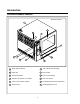
Introduction Convection Steamer Features Standard Features 10 6 11 5 4 7 12 1 8 2 3 9 1 Mode Selector Switch 7 DripĂCollectorĂ(self draining) 2 Timer Dial 8 Door Handle 3 Flush/Drain Switch 9 Door Contact Switch 4 Indicator Lamp (Red) Low Water" 10 VentĂ(not shown) 5 Power ON" Indicator (Green) 11 Decalcifying Inlet & Funnel Assembly 6 Steamer Door 12 Decalcifying Valve Lever 4
Installation Instructions THE INSTALLATION INSTRUCTIONS CONĆ TAINED HEREIN ARE FOR THE USE OF QUALIĆ FIED INSTALLATION AND SERVICE PERSONĆ NEL ONLY. INSTALLATION OR SERVICE BY OTHĆ ER THAN QUALIFIED PERSONNEL MAY REĆ SULT IN DAMAGE TO THE OVEN AND/OR INJUĆ RY TO THE OPERATOR.
Installation Convection Steamer Location and Ventilation The well planned and proper placement of the convection steamer will result in long term operĆ ator convenience and satisfactory performance. It is, therefore, urged that adequate thought be given to the location of the steamer prior to its delivery for installation. mable liquids and solvents.
Installation Installation and Connection HOT AND COLD WATER CONNECTION DRAIN CONNECTION Connect the appliance to quality hot and cold water via a pressure hose with 3/4" couplings. A shut off valve is to be provided adjacent to the unit. The Drain Vent assembly, included with the unit, and a 2 pipe with standard drain pitch, should be run to an open drain or connected to a standĆ pipe equipped with a vent. The waste water can also be directed to a nearby floor drain.
Installation Installation and Connection ELECTRICAL CONNECTIONS Before making any electrical connections to these units, check that the power supply is adeĆ quate for the voltage, amperage, and phase reĆ quirements stated on the rating name plate mounted on the unit. All steamers, when installed, must be electrically grounded in accordance with local codes or in the absence of local codes, with the National Electrical Code, ANSI/NFPA 70-Latest Edition and/or Canadian Electrical Code CSA C22.1 as applicable.
Installation Leg Attachment LEG VARIATIONS LEG ATTACHMENT 1. Align the threaded stud on one of the front legs to the bolt h ā oleā locatedāā ināā tā heā u ā nit'sā botĆ tom c ā orner. Turn the leg clockwise and tightĆ en to the nearest full turn. 2. Align the leg plate holes with the bolt holes. Secure with the two 1/2" bolts provided. 3. Repeat the above steps with the other front leg. If low profile casters are used, install them with the locking casters in the front of the oven.
Installation Stacking Ć Double Section Assembly STACKING PLUMBING 1. Attach copper Tee, gray hose and clamps to the drain outlet of both units. NOTE: The installation plumber is reĆ sponsible for connections beĆ tween units and connection to drain. Use a 24" section on top unit Tee to raise breather vent. See STEP 4. 1. Install 6" legs or casters on the bottom unit, using three .50Ć13 UNC bolts provided per leg or caster.
Installation Final Check and Adjustments BEFORE SWITCHING THE APPLIANCE ON DOOR ADJUSTMENT Before applying power to the unit for the first time, check for the following conditions: The door catch may be adjusted in two direcĆ tions, in and out, and up and down, using the folĆ lowing procedure: 1. All e ā lectricalā safety provisions have been adĆ hered to and the electrical connections are correct. 2. Water is connected, turned on and all of the connections are water tight. 1.
Operation Steamer StartĆUp and ShutĆDown STEAMER STARTĆUP Turn the mode switch to STEAM. STEAM MODE Turn the mode switch selector knob to the Steam Position. The green POWER" Indicator lamp illumiĆ nates on the front control panel. The steam generator will flush and drain automatically for 75 seconds if the unit has been off for at least 5 hours. The steam generator begins to fill.
Operation Control Panel 1. Indicator Light: LOW WATER, FILL This light flashes when the water level in the steam generator is too low. The appliance shuts off automatically in order to avoid damage. In this case, turn on the water tap or check to see if the flow of water is stopped (See the sections Adjustments" and Decalcifying"). 2. Indicator Light: POWER ON Lights up when the appliance is in operation. 3. Mode Selection To turn the appliance on, simply turn the Mode selector switch to STEAM.
Operation Mode Selection and Operation 1. Toāāturnāā the āappliance āon,ā āsimply āturn āthe āMode āSelector Switch (1) to STEAM: STEAM 1 2. Theāā POWER ONāā Indicatorāā Lightā (2)āā will lā ightā āup. 3. Set āthe āTIMER ā(3)ā āfor ātheā desiredāā steaming ātimeā or set āit toā āON. āThe ābuzzer āwill sound āand ātheā unitā will āshutā off when the time has expired. 4. At āthe āend āof āthe āspecified time period, the buzzer sounds andā theā appliance āwillā āshutā off a ā utomatically.
Maintenance Spray Bottle Operating Procedure 1. Unscrewāā tā heā sā prayerāā h ā ead a ā ndāā fā illā tā he conĆ tainer to the MAX mark. Screw the head asĆ sembly āon āfirmlyā toā āensureā āan āairtight seal. The liquid must be clean and free from forĆ eign matter. Do not overfill Ć space must be left for compressing air. 2. To build up pressure, pump approximately 20 full strokes when the container is filled with liquid. The higher the pressure, the finer the spray.
Maintenance Cleaning and Preventive Maintenance CLEANING THE STEAMER'S INTERIOR On stainless interiors deposits m ā ay b ā e rā emoved āwith āany of the following elements: Grade FFF Italian Pumice, Liquid Nu Steel, Permapass, SaĆ mea or Cameo Paste, Nu Steel or DuBois Temp. Heat tint or heavy discolorations may be reĆ moved with any of the following: PennyĆBrite, CopperĆBrite, DuBois Temp., Paste NuĆSteel, 5% to 15% nitric acid āor ā5% āto 15% phosphoric acid.
Maintenance Decalcification 5. Remove the Deliming Port Cap. Attach the supplied Funnel and Hose Assembly (3) to the deliming inlet. 1. Turn the Mode Selection Switch (1) to the STEAM mode. Wait until steam is produced. This will ensure that the water in the steam generator is hot. 6. Open the Deliming Port Valve (2) and pour in the deliming mixture. Stop pouring when the funnel stops draining. This is the correct amount for your site. 2.
Steaming Guide General Tips and Procedures CONTAINERS LOADING THE STEAMER Both solid and perforated steam table pans of varying sizes (full, half, and oneĆthird size) may be used in the Blodgett Combi Steamer. Small pans may be placed on wire racks. This flexibility makes the Combi Steamer an ideal tool for a wide variety of cooking needs, from full course meals to à la carte preparation. Place the food in the appropriate pans/trays or distribute it on the racks. Insert racks and trays into the pan rack.
Steaming Guide General Tips and Procedures TIPS AND PROCEDURES SAMPLE DISHES Stocks for Sauces Vegetables When trays are used for steaming there is usualĆ ly enough stock collected for making sauces. When using perforated pans, insert a solid pan in the bottom rack to collect the stock. Fresh and frozen vegetables may be steamed together. Frozen vegetables should be loosely scattered on the trays. Perforated trays shorten steaming time, although solid trays may be used.
Notes 20