CTB/CTBR SERIES ELECTRIC CONVECTION OVEN INSTALLATION -- OPERATION -- MAINTENANCE BLODGETT OVEN COMPANY www.blodgett.com 44 Lakeside Avenue, Burlington, Vermont 05401 USA Telephone (800) 331-5842, (802) 860-3700 Fax: (802)864-0183 PN 11361 Rev K (10/06) E 2006 --- G.S.
IMPORTANT WARNING: IMPROPER INSTALLATION, ADJUSTMENT, ALTERATION, SERVICE OR MAINTENANCE CAN CAUSE PROPERTY DAMAGE, INJURY OR DEATH. READ THE INSTALLATION, OPERATING AND MAINTENANCE INSTRUCTIONS THOROUGHLY BEFORE INSTALLING OR SERVICING THIS EQUIPMENT FOR YOUR SAFETY Do not store or use gasoline or other flammable vapors or liquids in the vicinity of this or any other appliance. The information contained in this manual is important for the proper installation, use, and maintenance of this oven.
THE REPUTATION YOU CAN COUNT ON For over a century and a half, The Blodgett Oven Company has been building ovens and nothing but ovens. We’ve set the industry’s quality standard for all kinds of ovens for every foodservice operation regardless of size, application or budget. In fact, no one offers more models, sizes, and oven applications than Blodgett; gas and electric, full-size, half-size, countertop and deck, convection, Cook’n Hold, Combi-Ovens and the industry’s highest quality Pizza Oven line.
Model: Your Service Agency’s Address: Serial Number: Your oven was installed by: Your oven’s installation was checked by:
Table of Contents Introduction Oven Description and Specifications . . . . . . . . . . . . . . . . . . . . . . . . . . . . . . . . Oven Components . . . . . . . . . . . . . . . . . . . . . . . . . . . . . . . . . . . . . . . . . . . . . . . 2 3 Installation Delivery and Location . . . . . . . . . . . . . . . . . . . . . . . . . . . . . . . . . . . . . . . . . . . . . Stand Assembly . . . . . . . . . . . . . . . . . . . . . . . . . . . . . . . . . . . . . . . . . . . . . . . . . Stand Options . . . . . .
Introduction Oven Description and Specifications Blodgett convection ovens represent the latest advancement in energy efficiency, reliability, and ease of operation. Heat normally lost, is recirculated within the cooking chamber before being vented from the oven: resulting in substantial reductions in energy consumption and enhanced oven performance.
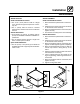
Introduction Oven Components Rack Supports --- hold oven racks. Heating Elements --- located on the side of the oven, the elements provide heat to the baking chamber on electric ovens. Blower Wheel Cover --- located on the side interior wall of the oven. Protects the blower wheel. Control Panel --- contains wiring and components to control the oven operation. Blower Wheel --- spins to circulate hot air in the baking chamber. Oven Racks --- five racks are provided standard.
Installation Delivery and Location DELIVERY AND INSPECTION OVEN LOCATION All Blodgett ovens are shipped in containers to prevent damage. Upon delivery of your new oven: The well planned and proper placement of your oven will result in long term operator convenience and satisfactory performance. D D Inspect the shipping container for external damage. Any evidence of damage should be noted on the delivery receipt which must be signed by the driver. Uncrate the oven and check for internal damage.
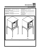
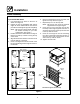
Installation Stand Assembly STAND OPTIONS STAND ASSEMBLY Small Stands Without Shelves Small Stands Without Shelves D D 1. Place stand frame upside down on a work surface. 2. Attach one leg to each of the corner stud bolts on the bottom of the stand top. 3. Place a lock washer and nut on each stud, and tighten securely. 4. The stand is now ready for the oven assembly. The 5-3/4” (15cm) stand is used for a single oven, when short legs are required for countertop use.
Installation Stand Assembly Open Stands With Racks 6. Place a lock washer and nut on each bolt, and tighten securely. See the Figure 2. 7. Repeat Steps 3---6 for the top shelf. NOTE: Be sure the slots in the top shelf are aligned with the support angles. 8. Insert the top of the rack stops into the two back clips on the angle supports as shown. Insert the bottom of the rack stops into the slots in the top shelf as shown. 9.
Installation Oven Assembly OVEN ASSEMBLY TO STAND Single Section Double Section 1. Place the assembled stand in the location where the oven is going to be used. 2. Remove the side control compartment cover and open the front control panel of a single oven (or lower section). 3. With a tool, punch out the knock-outs in the oven bottom near each corner. 4. Set the oven on the stand. Center it to the frame. 5. Align the front, and rear bolt holes of the oven with the bolt holes in the stand. 6.
Installation Oven Assembly 4” (10CM) LEG ATTACHMENT 1. Lay the oven on its side. 2. Screw one leg into each of the corner nuts. OVEN LEVELING After assembly, the oven should be leveled and moved to the operating location. 1. The oven can be leveled by adjusting the feet or casters located on the bottom of each leg. ADJUSTMENTS ASSOCIATED WITH INITIAL INSTALLATION Each oven, and its component parts, have been thoroughly tested and inspected prior to shipment.
Installation Utility Connections --- Standards and Codes U.S. and Canadian installations THE INSTALLATION INSTRUCTIONS CONTAINED HEREIN ARE FOR THE USE OF QUALIFIED INSTALLATION AND SERVICE PERSONNEL ONLY. INSTALLATION OR SERVICE BY OTHER THAN QUALIFIED PERSONNEL MAY RESULT IN DAMAGE TO THE OVEN AND/OR INJURY TO THE OPERATOR.
Installation Electrical Connection 1. The supply conduit enters through the rear of the oven and electrical block secured to the perforated panel at the back of the control compartment. Wiring diagrams are located in the control compartment area. Ovens are supplied for operation in several voltage choices, single or three phase grounded circuits. THE BLODGETT OVEN COMPANY CANNOT ASSUME RESPONSIBILITY FOR LOSS OR DAMAGE SUFFERED AS A RESULT OF IMPROPER INSTALLATION.
Operation Safety Information THE INFORMATION CONTAINED IN THIS SECTION IS PROVIDED FOR THE USE OF QUALIFIED OPERATING PERSONNEL. QUALIFIED OPERATING PERSONNEL ARE THOSE WHO HAVE CAREFULLY READ THE INFORMATION CONTAINED IN THIS MANUAL, ARE FAMILIAR WITH THE FUNCTIONS OF THE OVEN AND/OR HAVE HAD PREVIOUS EXPERIENCE WITH THE OPERATION OF THE EQUIPMENT DESCRIBED. ADHERENCE TO THE PROCEDURES RECOMMENDED HEREIN WILL ASSURE THE ACHIEVEMENT OF OPTIMUM PERFORMANCE AND LONG, TROUBLE-FREE SERVICE.
Operation Solid State Manual COMPONENT DESCRIPTION 1. SELECTOR SWITCH - controls power to the oven and selects Cool Down mode. 2. PANEL MOUNT FUSE HOLDERS - provide oven circuit protection. 3. OVEN READY LIGHT - when lit, indicates heater operation. When the light goes out, the oven has reached operating temperature. 4. COOK THERMOSTAT - controls oven temperature at the desired setting. Thermostat is available in either infinite (shown) or set point control.
Operation Solid State Digital COMPONENT DESCRIPTION 1. SELECTOR SWITCH - turns power to the oven on or off. Allows selection of Cook or Cool Down modes and fan speed (if applicable). 2. DISPLAY - displays time, temperature, or other information related to oven function. 3. HEAT LAMP - lights when heater is on. 4. PULSE LAMP - lights when Pulsed Fan Mode is turned on. 5. HOLD LAMP - lights when Hold Mode is turned on. 6. DIAL - used to enter set points in display. 7.
Operation Solid State Digital OPERATION Cook with Pulse Cook NOTE: The PULSE light is on when pulse mode is on and off when pulse mode is off. 1. Turn the SELECTOR SWITCH (1) to the desired position. 2. Enter the cook time and temperature. 3. Load product into the oven. NOTE: The display reads LOAD when the oven is near set temperature. 4. Push the START/STOP key (7). The timer begins to count down. 5. When the cook timer reaches 00:00 the buzzer sounds and the display reads DONE. 6.
Operation Fan Delay and Pulse Plus Control COMPONENT DESCRIPTION 1. SELECTOR SWITCH - controls power to the oven for cook and cool down positions 2. PANEL MOUNT FUSE HOLDERS - provide oven circuit protection. 3. AMBER FAN DELAY LIGHT - indicates the oven is in pulse plus. 4. FAN DELAY TIMER - activates pulse plus for 0-10 minutes. The blower and burners pulse on for 30 seconds and off for 30 seconds for the duration of time set. 5. RED INDICATOR LIGHT - indicates the oven is in the cook timer cycle. 6.
Operation Cook and Hold COMPONENT DESCRIPTION 1. SELECTOR SWITCH - controls power to the oven and selects cool down mode. 2. PANEL MOUNT FUSE HOLDERS - provide oven circuit protection. 3. OVEN READY LIGHT - when lit, indicates heater operation. When the light goes out, the oven has reached operating temperature. 4. COOK THERMOSTAT - controls oven temperature in the cook cycle. 5. COOK TIMER - activates an electric buzzer that sounds when the cook time expires. 6.
Operation Cook and Hold CONTROL OPERATION Cook Only 1. Turn the SELECTOR SWITCH (1) to COOK. 2. Set the COOK THERMOSTAT (4) to the desired temperature. 3. Preheat the oven until the OVEN READY LIGHT (3) goes out. 4. Load product into the oven. Set the COOK TIMER (5) to the desired cook time. 5. When the buzzer sounds, remove the product. Turn the COOK TIMER (5) to OFF to silence the buzzer. 6. Turn the SELECTOR SWITCH (1) to OVEN OFF. Cook and Hold 1. Turn the SELECTOR SWITCH (1) to COOK. 2.
Operation CH-Pro3 (Solid State Programmable Digital Control) COMPONENT DESCRIPTION 1. SELECTOR SWITCH --- turns power to the oven on or off. Allows selection of cook or cool down modes and fan speed (if applicable). 2. TIME DISPLAY --- gives cook time. 3. TIME ARROW KEYS --- press to enter cook and/ or pulse times. 4. READY INDICATOR --- when lit indicates the oven has reached the setpoint temperature and product may be loaded. 5. TEMPERATURE DISPLAY --- gives cook and hold temperatures. 6.
Operation CH-Pro3 (Solid State Programmable Digital Control) MANUAL OPERATION NOTE: Press the arrow keys to change the cook time and temperature at any point duringmanual operation. Cook Only: 1. Turn the SELECTOR SWITCH (1) to the desired position. 2. Press the MANUAL PRODUCT KEY (12). The manual and fan key LEDs light. 3. Press the TIME ARROW KEYS (3) to enter the cook time. 4. Press the TEMPERATURE ARROW KEYS (7) to enter the cook temperature. 5.
Operation CH-Pro3 (Solid State Programmable Digital Control) PROGRAMMING THE MANUAL KEY DEFAULT PROGRAMMING THE PRODUCT KEYS 1. Turn the SELECTOR SWITCH (1) to the desired position. 2. Press the MANUAL KEY (12). The manual and fan key LEDs light. 1. Turn the SELECTOR SWITCH (1) to the desired position. 2. Press the desired PRODUCT KEY (11). The product and fan key LEDs light. 3. Press the PROGRAM KEY (14). 3.
Operation Blodgett IQ2T Control COMPONENT DESCRIPTION 1. OVEN POWER SWITCH --- controls power to the oven. 2. TOP DISPLAY --- displays temperature and other controller related information. 3. FAN HI LED --- when lit indicates the fan is running at high speed. 4. BOTTOM DISPLAY --- displays cook time and other controller related information. 5. PROG LED --- when lit indicates the controller is in the programming mode. 6. HEAT LED --- when lit indicates the control is calling for heat. 7.
Operation Blodgett IQ2T Control OVEN OPERATION Oven Startup: 1. Toggle the POWER SWITCH (1) to ON. The oven preheats to the lowest programmed first stage temperature. The LEDS (16) for all products with the same first stage temperature light. While the unit preheats the TOP DISPLAY (2) gives the set temperature. The BOTTOM DISPLAY (4) reads Lo if the oven is more than 10_ below setpoint. When the oven reaches ¦10_ of the preheat temperature an alarm sounds and the bottom display reads Ready.
Operation Blodgett IQ2T Control 3. Load the second product. Press the appropriate PRODUCT KEY (17). Press a SHELF KEY (18) to activate shelf timing. NOTE: Only products with lighted LEDS may be selected. 4. The top display reads SHLF. The bottom display gives the numbers of the shelves that have been assigned. Within five seconds the shelf with the least amount of time remaining is displayed. The led for the product with the least time remaining flashes faster than the led for the other products.
Operation Blodgett IQ2T Control PROGRAMMING SINGLE STAGE RECIPES Entering the Programming Mode: 1. Press and hold the PROG KEY (10). The top display reads CodE. 2. Use the product keys to enter the programming access code: 3 1 2 4. Press the ENTER KEY (14). The top display reads Prod. 3. Press the desired product key followed by the ENTER KEY (14). NOTE: During the programming process you may: Press the TOGGLE/CLEAR KEY (11) to erase the current setting or toggle between specific settings.
Operation Blodgett IQ2T Control Programming the Shelf ID: Programming Hold Mode: The Shelf ID option can be turned on or off for specific product keys. The hold mode can be toggled on or off for specific product keys. 1. The top display reads HOLD. The bottom display reads the current hold mode. Press TOGGLE/CLEAR KEY (11) to toggle between on and off. Press the SCAN KEY (15). 2. If the hold mode is activated, the bottom display give the current hold time. Press the TOGGLE/CLEAR KEY (11).
Operation Blodgett IQ2T Control PROGRAMMING MULTIPLE STAGE RECIPES Entering the Programming Mode: 1. Press and hold the PROG KEY (10). The top display reads CodE. 2. Use the product keys to enter the programming access code: 3 1 2 4. Press the ENTER KEY (14). The top display reads Prod. 3. Press the desired product key followed by the ENTER KEY (14). Programming the Cook Time: NOTE: When multiple stage cooking is being used, the countdown time displayed during cooking is the sum of all stages. 1.
Operation Blodgett IQ2T Control Programming the Fan Cycle Time: Programming the Timing Mode: There are 3 options for fan cycle time: Pulse, Heat and Full. Pulse allows the fan to turn on and off as programmed. Heat allows the fan to operate with heat only. Full provides continuous fan operation. NOTE: It may be necessary to press the ENTER KEY (14) until the top display reads tC ---1. 1. The top display reads CYC1. The bottom display gives the current fan cycle for stage 1.
Operation Blodgett IQ2T Control MANAGER LEVEL PROGRAMMING Programming the setback mode Entering the programming mode The setback mode operates as a power saving feature. After a period of non-use (the setback time) the oven temperature automatically decreases to the setback temperature. The oven will maintain this temperature until a product key is pressed. The minimum setback time is 20:00. 1. Press the PROG KEY (10). The top display reads CodE. 2.
Operation Blodgett IQ2T Control Programming the shelf sensitivity ERROR CODES AND ALARMS The controller allows the user to program a sensitivity value (0---9) for each shelf position. The sensitivity value will shorten or stretch cook time depending upon shelf position. NOTE: The error codes will appear in the top display. All error codes are accompanied by an audible alarm. Hi Oven temperature is more than 40_F above the highest setpoint.
Operation How Cook and Hold Works With the optional COOK & HOLD feature, meat is roasted at lower temperatures for longer periods of time. This preserves flavor and tenderness and prevents over drying. There are three phases in cook and hold roasting. D D 225_ 200_ Primary Cooking --- controlled by the COOK & HOLD TIMER. The meat is cooked at a low temperature until approximately 2/3 done. Cooking from Stored Heat --- when the primary cook time expires, the oven automatically switches to HOLD.
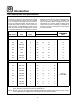
Operation General Guidelines for Operating Personnel COOK TIMES AND TEMPERATURES OPERATING TIPS Preheating the oven Pans and Racks Always preheat the oven before baking or roasting. We recommend preheating 50_F (10_C) above the cook temperature to offset the drop in temperature when the doors are opened and cold product is loaded into the oven. Set the thermostat to the cook temperature after the product is loaded. Product or pan height determines how many racks are used. The oven holds up to 9 racks.
Operation Suggested Times and Temperatures Product Temperature Time # Shelves 400_F (205_C) 275_F (135_C) 235_F (115_C) 450_F (235_C) 275_F (135_C) 375_F (190_C) 300_F (150_C) 400_F (205_C) 400_F (205_C) 8-10 mins. 2 hrs 45 mins. 2 hrs 45 mins. 7-8 mins. 1 hr. 25-30 mins. 3 hrs. 10 mins. 7-8 mins. 5-7 mins. 10 2 2 5 5 5 2 5 10 350_F (175_C) 350_F (175_C) 350_F (175_C) 310_F (155_C) 40 mins. 35 mins. 30 mins. 3 hrs 45 mins. 5 5 5 3 350_F (175_C) 400_F (205_C) 425_F (220_C) 20 mins. 10 mins.
Maintenance Cleaning and Preventative Maintenance CLEANING THE OVEN PREVENTATIVE MAINTENANCE Painted and stainless steel ovens may be kept clean and in good condition with a light oil. 1. Saturate a cloth, and wipe the oven when it is cold. 2. Dry the oven with a clean cloth. The best preventative maintenance measures are, the proper installation of the equipment and a program for routinely cleaning the ovens.
Maintenance Troubleshooting Guide POSSIBLE CAUSE(S) SUGGESTED REMEDY SYMPTOM: Heating elements do not come on. S S S S S Oven not plugged in. S Power switch on the control panel is off. S Control set below ambient temperature. S Doors are open. S Computerized controls --- error code on display. S Plug in electrical supply cord. Set the control panel to COOK or OVEN ON. Set to desired cook temperature. Close doors. * SYMPTOM: Oven does not come to ready.
CUSTOMER INSERT WIRING DIAGRAM HERE