ZEPHAIRE-E ELECTRIC CONVECTION OVEN INSTALLATION -- OPERATION -- MAINTENANCE BLODGETT OVEN COMPANY www.blodgett.com 44 Lakeside Avenue, Burlington, Vermont 05401 USA Telephone (800) 331-5842, (802) 860-3700 Fax: (802)864-0183 PN 90147 Rev H (10/06) E 2006 --- G.S.
IMPORTANT WARNING: IMPROPER INSTALLATION, ADJUSTMENT, ALTERATION, SERVICE OR MAINTENANCE CAN CAUSE PROPERTY DAMAGE, INJURY OR DEATH. READ THE INSTALLATION, OPERATING AND MAINTENANCE INSTRUCTIONS THOROUGHLY BEFORE INSTALLING OR SERVICING THIS EQUIPMENT FOR YOUR SAFETY Do not store or use gasoline or other flammable vapors or liquids in the vicinity of this or any other appliance. The information contained in this manual is important for the proper installation, use, and maintenance of this oven.
THE REPUTATION YOU CAN COUNT ON For over a century and a half, The Blodgett Oven Company has been building ovens and nothing but ovens. We’ve set the industry’s quality standard for all kinds of ovens for every foodservice operation regardless of size, application or budget. In fact, no one offers more models, sizes, and oven applications than Blodgett; gas and electric, full-size, half-size, countertop and deck, convection, Cook’n Hold, Combi-Ovens and the industry’s highest quality Pizza Oven line.
Model: Your Service Agency’s Address: Serial Number: Your oven was installed by: Your oven’s installation was checked by:
Table of Contents Introduction Oven Description and Specifications . . . . . . . . . . . . . . . . . . . . . . . . . . . . . . . . Oven Components . . . . . . . . . . . . . . . . . . . . . . . . . . . . . . . . . . . . . . . . . . . . . . . 2 3 Installation Delivery and Location . . . . . . . . . . . . . . . . . . . . . . . . . . . . . . . . . . . . . . . . . . . . . Utility Connections --- Standards and Codes . . . . . . . . . . . . . . . . . . . . . . . . . Oven Assembly . . . . . . . . . . . . . . . .
Introduction Oven Description and Specifications Cooking in a convection oven differs from cooking in a conventional deck or range oven since heated air is constantly recirculated over the product by a fan in an enclosed chamber. The moving air continually strips away the layer of cool air surrounding the product, quickly allowing the heat to penetrate. The result is a high quality product, cooked at a lower temperature in a shorter amount of time.
Introduction Oven Components Heating Elements --- located in the back of the oven, the elements provide heat to the baking chamber on electric ovens. Baffle --- located on the back interior wall of the oven. Protects the blower wheel. Blower Wheel --- spins to circulate hot air in the baking chamber. Control Panel --- contains wiring and components to control the oven operation. Blower Motor --- provides power to turn the blower wheel. Oven Racks --- five racks are provided standard.
Installation Delivery and Location DELIVERY AND INSPECTION OVEN LOCATION All Blodgett ovens are shipped in containers to prevent damage. Upon delivery of your new oven: The well planned and proper placement of your oven will result in long term operator convenience and satisfactory performance. D D Inspect the shipping container for external damage. Any evidence of damage should be noted on the delivery receipt which must be signed by the driver. Uncrate the oven and check for internal damage.
Installation Utility Connections --- Standards and Codes U.S. and Canadian installations THE INSTALLATION INSTRUCTIONS CONTAINED HEREIN ARE FOR THE USE OF QUALIFIED INSTALLATION AND SERVICE PERSONNEL ONLY. INSTALLATION OR SERVICE BY OTHER THAN QUALIFIED PERSONNEL MAY RESULT IN DAMAGE TO THE OVEN AND/OR INJURY TO THE OPERATOR.
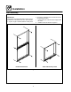
Installation Oven Assembly NSF BOLTS any holes in stacked units not used for mounting stacking brackets. 1. Locate the 5/16” bolts that were shipped with the oven. 2. Install the bolts as shown in Figure 3. D These bolts are required by NSF to block any exposed hole on the back of an oven. This includes: D any unit, single or stacked, without a back panel.
Installation Oven Assembly LEG ATTACHMENT 1. Lay the oven on its back. 2. Align the threaded stud in each leg with the nut located inside each bottom corner of the oven frame. Turn the legs clockwise and tighten to the nearest full turn. 3. Align the two leg plate holes in each leg with those in the oven bottom. Secure each leg using two 1/2” bolts. NOTE: If using casters see CASTER ASSEMBLY before proceeding. 4. Tip the oven up on the legs. 5.
Installation Oven Assembly DOUBLE SECTION ASSEMBLY 3. Attach the stacking brackets using the remaining 5/16” bolts shipped with the ovens. 4. Drill a clearance hole for a 5/16” bolt in the angle iron of the old style oven. Use the holes in the stacking brackets as a pilot. 5. Attach the stacking brackets to the old style oven with the 5/16” bolts and nuts provided in the kit. 6. Attach the flue connector. NOTE: Old style ovens refer to units with painted exposed rear angle.
Operation Single Speed Blower 1 ON MAN OFF AUTO BLOWER COOL DOWN THE INFORMATION CONTAINED IN THIS SECTION IS PROVIDED FOR THE USE OF QUALIFIED OPERATING PERSONNEL. QUALIFIED OPERATING PERSONNEL ARE THOSE WHO HAVE CAREFULLY READ THE INFORMATION CONTAINED IN THIS MANUAL, ARE FAMILIAR WITH THE FUNCTIONS OF THE OVEN AND/OR HAVE HAD PREVIOUS EXPERIENCE WITH THE OPERATION OF THE EQUIPMENT DESCRIBED.
Operation Single Speed Blower with Cavity Lights CONTROL DESCRIPTION 1 2 ON ON MAN OFF OFF AUTO LIGHTS BLOWER 1. CAVITY LIGHTS ON/OFF --- Operates the oven cavity lights. 2. BLOWER ON/OFF SWITCH --- Controls the operation of the blower. If the blower switch is in the OFF position the oven will be turned off. 3. COOL DOWN SWITCH --- When the switch is in the AUTO position, the oven can be used to cook. When the switch is in the MAN position, the oven is cooling down for the next bake. 4.
Operation Dual Speed Blower CONTROL DESCRIPTION 1 HI MAN OFF LOW BLOWER 1. BLOWER HI/LO/OFF SWITCH --- Controls the operation of the blower. If the blower switch is in the OFF position the oven will be turned off. 2. COOL DOWN SWITCH --- When the switch is in the AUTO position, the oven can be used to cook. When the switch is in the MAN position, the oven is cooling down for the next bake. 3. OVEN READY LIGHT - When lit indicates elements are heating.
Operation Dual Speed Blower with Cavity Lights CONTROL DESCRIPTION 1 ON MAN OFF OFF 2 HI LOW LIGHTS BLOWER 1. CAVITY LIGHTS ON/OFF --- Operates the oven cavity lights. 2. BLOWER HI/LO/OFF SWITCH --- Controls the operation of the blower. If the blower switch is in the OFF position the oven will be turned off. 3. COOL DOWN SWITCH --- When the switch is in the AUTO position, the oven can be used to cook. When the switch is in the MAN position, the oven is cooling down for the next bake. 4.
Operation General Guidelines for Operating Personnel COOK TIMES AND TEMPERATURES OPERATING TIPS Preheating the oven Pans and Racks Always preheat the oven before baking or roasting. We recommend preheating 50_F (10_C) above the cook temperature to offset the drop in temperature when the doors are opened and cold product is loaded into the oven. Set the thermostat to the cook temperature after the product is loaded. Product or pan height determines how many racks are used.
Operation Suggested Times and Temperatures Product Temperature Time # Shelves Meats Hamburger Patties (5 per lb) Steamship Round (80 lb. quartered) Standing Rib Choice (20 lbs, trimmed, rare) Banquet Shell Steaks (10 oz. meat) Swiss Steak after Braising Baked Stuffed Pork Chop Boned Veal Roast (15 lbs.) Lamb Chops (small loin) Bacon (on racks in 18” x 26” pans) 400_F (205_C) 275_F (135_C) 235_F (115_C) 450_F (235_C) 275_F (135_C) 375_F (190_C) 300_F (150_C) 400_F (205_C) 400_F (205_C) 8-10 mins.
Maintenance Cleaning and Preventative Maintenance CLEANING THE OVEN PREVENTATIVE MAINTENANCE Stainless steel ovens may be kept clean and in good condition with a light oil. 1. Saturate a cloth, and wipe the oven when it is cold. 2. Dry the oven with a clean cloth. The best preventative maintenance measures are, the proper installation of the equipment and a program for routinely cleaning the ovens.
Maintenance Troubleshooting Guide POSSIBLE CAUSE(S) SUGGESTED REMEDY SYMPTOM: Elements will not heat S S S S Oven not plugged in. S S S S Power switch on the control panel is off. Control set below ambient temperature. Doors are open. Plug in electrical supply cord. Set the control panel to COOK or OVEN ON. Set to desired cook temperature. Close doors. SYMPTOM: Oven does not come to ready. S The oven has not reached preheat temperature. S Wait for oven to reach preheat temperature.
CUSTOMER INSERT WIRING DIAGRAM HERE