DFG-100 & DFG-200 GAS CONVECTION OVENS INSTALLATION - OPERATION - MAINTENANCE BLODGETT OVEN COMPANY www.blodgett.com 44 Lakeside Avenue, Burlington, Vermont 05401 USA Telephone: (802) 658-6600 Fax: (802)864-0183 PN 90055 Rev AG (10/15) © 2015 - G.S.
Your Service Agency’s Address: Model Serial number Oven installed by Installation checked by
TABLE OF CONTENTS IMPORTANT WARNING: Improper installation, adjustment, alternation, service or maintenance can cause property damage, injury or death. Read the instllation, operation and maintenance instructions thoroughly before installing or servicing this equipment. INSTRUCTIONS TO BE FOLLOWED IN THE EVENT THE USER SMELLS GAS MUST BE POSTED IN A PROMINENT LOCATION. This information may be obtained by contacting your local gas supplier.
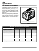
Installation Oven Description and Specifications Cooking in a convection oven differs from cooking in a conventional deck or range oven since heated air is constantly recirculated over the product by a fan in an enclosed chamber. The moving air continually strips away the layer of cool air surrounding the product, quickly allowing the heat to penetrate. The result is a high quality product, cooked at a lower temperature in a shorter amount of time.
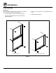
Installation Delivery and Location DELIVERY AND INSPECTION The following clearances must be available for servicing. All Blodgett ovens are shipped in containers to prevent damage. Upon delivery of your new oven: • Oven body sides - 12” (30cm) • Oven body back - 12” (30cm) • Inspect the shipping container for external damage. Any evidence of damage should be noted on the delivery receipt which must be signed by the driver. • Uncrate the oven and check for internal damage.
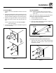
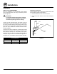
Installation Oven Assembly NSF BOLTS These bolts are required by NSF to block any exposed hole on the back of an oven. This includes: 1. Locate the 5/16” bolts that were shipped with the oven. • any unit, single or stacked, without a back panel. 2. Install the bolts as shown. • any holes in stacked units not used for mounting stacking brackets.
Installation Oven Assembly LEG ATTACHMENT CASTER ASSEMBLY 1. Push the oven onto a lift with the bottom of the oven down. NOTE: Install the locking casters on the front of the oven. Install the non-locking casters on the back of the oven. 2. Align the threaded stud in each leg with the nut located inside each bottom corner of the oven frame. Turn the legs clockwise and tighten to the nearest full turn. NOTE: Use a gas hose restraint on all units with casters.
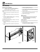
Installation Oven Assembly DOUBLE SECTION ASSEMBLY 3. Attach the stacking brackets using the remaining 5/16” bolts shipped with the ovens. NOTE: Old style ovens refer to units with painted exposed rear angle. New style ovens refer to units with rear angle iron enclosed in steel. 4. Drill a clearance hole for a 5/16” bolt in the angle iron of the old style oven. Use the holes in the stacking brackets as a pilot. The following instructions apply to stacking two new style ovens. 5.
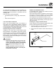
Installation Ventilation CANOPY TYPE EXHAUST HOOD On gas models the installation of a proper ventilation system cannot be over emphasized. This system removes unwanted vapors and products of combustion from the operating area. A mechanically driven, canopy type exhaust hood is the preferred method of ventilation. The hood should be sized to completely cover the equipment plus an overhang of at least 6” (15 cm) on all sides not adjacent to a wall.
Installation Ventilation DIRECT FLUE ARRANGEMENT Installing the draft hood When the installation of a mechanically driven exhaust hood is impractical the oven may be vented by a direct flue arrangement. Ovens ordered for direct venting are supplied with a draft hood. Install the draft hood as follows: 1. Place the draft hood over the flue connector. 2. Secure both ends with the sheet metal screws provided. WARNING!! It is essential that the direct flue be installed as follows.
Installation Utility Connections - Standards and Codes U.S. and Canadian installations THE INSTALLATION INSTRUCTIONS CONTAINED HEREIN ARE FOR THE USE OF QUALIFIED INSTALLATION AND SERVICE PERSONNEL ONLY. INSTALLATION OR SERVICE BY OTHER THAN QUALIFIED PERSONNEL MAY RESULT IN DAMAGE TO THE OVEN AND/OR INJURY TO THE OPERATOR. Installation must conform with local codes, or in the absence of local codes, with the National Fuel Gas Code, NFPA54/ANSI Z223.
Installation Gas Connection GAS PIPING Maximum Capacity of Iron Pipe in Cubic Feet of Natural Gas Per Hour A properly sized gas supply system is essential for maximum oven performance. Piping should be sized to provide a supply of gas sufficient to meet the maximum demand of all appliances on the line without loss of pressure at the equipment. (Pressure drop of 0.5 Inch W.C.
Installation Gas Connection PRESSURE REGULATION AND TESTING Each oven is supplied with a regulator to maintain the proper gas pressure. The regulator is essential to the proper operation of the oven and should not be removed. It is preset to provide the oven with 3.5” W.C. (0.87 kPa) for natural gas and 10.0” W.C. (2.50 kPa) for Propane at the manifold. DFG-100-3 ovens are rated at 55,000 BTU/Hr. (16.2 kW) (58 MJ) per section. DFG-200-L ovens are rated at 60,000 BTU/Hr. (17.6 kW) (63 MJ) per section.
Installation Gas Connection GAS HOSE RESTRAINT WARNING!! If the oven is mounted on casters, a commercial flexible connector with a minimum of 3/4” (1.9 cm) inside diameter must be used along with a quick connect device. If the restraint is disconnected for any reason it must be reconnected when the oven is returned to its original position. The restraint, supplied with the oven, must be used to limit the movement of the unit so that no strain is placed upon the flexible connector.
Installation Electrical Connection Wiring diagrams are located in the control compartment and on the back of the oven. WARNING!! This appliance is equipped with three prong grounding type plug for your protection against shock hazard and should be plugged directly into a properly grounded three prong receptacle. DO NOT cut or remove the grounding prong from this plug. This oven is supplied for connection to 115 volt grounded circuits.
Installation Initial Startup Adjustments associated with initial installation The following is a check-list to be completed by qualified personnel prior to turning on the appliance for the first time. 3. Turn the combination valve’s manual shut-off to the on position. Each oven, and its component parts, have been thoroughly tested and inspected prior to shipment. However, it is often necessary to further test or adjust the oven as part of a normal and proper installation.
Operation Safety Information What to do in the event of a power failure: The information contained in this section is provided for the use of qualified operating personnel. Qualified operating personnel are those who have carefully read the information contained in this manual, are familiar with the functions of the oven and/or have had previous experience with the operation of the equipment described.
Operation SSI-D Solid State Infinite Control with Digital Timer CONTROL DESCRIPTION 1. SELECTOR SWITCH - controls power to the oven for cook or cool down. 1 2. BLOWER SWITCH - controls blower speed, either hi or lo. 3. LIGHTS SWITCH - controls interior lights. 4. OVEN READY LIGHT - when lit indicates burner operation. When the light goes out the oven has reached operating temperature. 5. SOLID STATE THERMOSTAT - allows an infinite selection of temperatures from 150-500°F (66-260°C). 2 3 6.
Operation SSI-M Solid State Infinite Control with Manual Timer CONTROL DESCRIPTION 1. SELECTOR SWITCH - controls power to the oven for cook or cool down. 1 2. BLOWER SWITCH - controls blower speed, either hi or lo. Two speed not available in 50 Hz. 3. LIGHTS SWITCH - controls interior lights. 4. OVEN READY LIGHT - when lit indicates burner operation. When the light goes out the oven has reached operating temperature. 2 3 5.
Operation SSD Solid State Digital Control CONTROL DESCRIPTION 1. SELECTOR SWITCH - turns power to the oven on or off. Allows selection of Cook or Cool Down Modes and fan speed (if applicable). 1 2. BLOWER SWITCH - controls blower speed, either hi or lo. Two speed not available in 50 Hz. 3. LIGHTS SWITCH - controls interior lights. 4. DISPLAY - displays time or temperature and other information related to oven function. 5. HEAT LAMP - lights when heater is on. 2 3 6.
Operation SSD Solid State Digital Control TO SET THE PULSE TIME: Cook with Pulse: 1. Press PULSE KEY (13) to turn pulse mode on. NOTE: PULSE light is on when pulse mode is on and off when pulse mode is off. NOTE: Pulse light is on. 1. Turn the SELECTOR SWITCH (1) to the desired position. 2. Rotate DIAL (8) to enter the pulse time. Pulse time is a portion of the pre-set cook time. 2. Enter cook time and cook temperature. OPERATION 3. Press PULSE KEY (13). Enter the pulse time.
Operation How Cook & Hold Works With the optional COOK & HOLD feature, meat is roasted at lower temperatures for longer periods of time. This preserves flavor and tenderness and prevents over drying. There are three phases in cook and hold roasting. Primary Cooking - controlled by the COOK & HOLD TIMER. The meat is cooked at a low temperature until approximately 2/3 done. • Cooking from Stored Heat - when the primary cook time expires, the oven automatically switches to HOLD.
Operation General Guidelines for Operating Personnel COOK TIMES AND TEMPERATURES OPERATING TIPS Preheating the oven Pans and Racks Always preheat the oven before baking or roasting. We recommend preheating 50°F (28°C) above the cook temperature to offset the drop in temperature when the doors are opened and cold product is loaded into the oven. Set the thermostat to the cook temperature after the product is loaded. Product or pan height determines how many racks are used.
Operation Suggested Times and Temperatures PRODUCT TEMPERATURE TIME # SHELVES Hamburger Patties (5 per lb) 400°F (205°C) 8-10 mins. 10 Steamship Round (80 lb. quartered) 275°F (135°C) 2 hrs 45 mins. 2 Standing Rib Choice (20 lbs, trimmed, rare) 235°F (115°C) 2 hrs 45 mins. 2 Banquet Shell Steaks (10 oz. meat) 450°F (235°C) 7-8 mins. 5 Swiss Steak after Braising 275°F (135°C) 1 hr. 5 Baked Stuffed Pork Chop 375°F (190°C) 25-30 mins. 5 Boned Veal Roast (15 lbs.
Maintenance Cleaning and Preventative Maintenance CLEANING THE OVEN Weekly Cleaning Be sure the air intake (cooling fan) behind the oven is free of all lint, grease or other air flow inhibitors. Keeping the air intake free of obstructions will extend the life of the oven components. WARNING!! Always clean the unit when it is cold. WARNING!! PREVENTATIVE MAINTENANCE Be sure to read and follow the MSDS or safety instructions on the bottle for your oven cleaner.
Maintenance Troubleshooting Guide POSSIBLE CAUSE(S) SYMPTOM: Oven will not fire. • Gas turned off. SUGGESTED REMEDY • Turn the gas valve to ON. • Oven not plugged in. • Plug in electrical supply cord. • Power switch on the control panel is off. • Set the control panel to COOK or OVEN ON. • Control set below ambient temperature. • Set to desired cook temperature. • Doors are open. • Close doors. • Computerized controls - error code on display. • * SYMPTOM: Oven does not come to ready.