
Installation and Operation Manual


8
Installation
Ventilation
DIRECT FLUE ARRANGEMENT
When the installation of a mechanically driven exhaust
hood is impractical the oven may be vented by a direct
ue arrangement.
WARNING!!
It is essential that the direct ue be installed
as follows. Incorrect installation will result in
unsatisfactory baking and oven damage.
The ue must be class B or better. The height of the ue
should rise 6-8 ft (2-2.5 m) above the roof of the build-
ing or any proximate structure. Never direct vent the oven
into a hood. The ue should be capped with a UL Listed
type vent cap to isolate the unit from external environ-
mental conditions.
The direct vent cannot replace air consumed and vented
by the oven. Provisions must be made to supply the room
with sufcient make-up air. Total make-up air require-
ments for each oven section should be approximately 30
CFM (.85 m3) per section. To increase the supply air en-
tering the room, a ventilation expert should be consulted.
FLUE DIAMETER
Oven Single Double
DFG-100 6” (15cm) 6” (15cm)
DFG-200 6” (15cm) 8” (20cm)
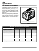
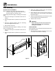
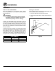
Installing the draft hood
Ovens ordered for direct venting are supplied with a draft
hood. Install the draft hood as follows:
1. Place the draft hood over the ue connector.
2. Secure both ends with the sheet metal screws pro-
vided.
Flue
Drafthood
Front of
Oven
Figure 8