HV-100E, HV-100G, HVH-100E and HVH-100G INSTALLATION - OPERATION - MAINTENANCE BLODGETT OVEN COMPANY www.blodgett.com 44 Lakeside Avenue, Burlington, Vermont 05401 USA Telephone: (802) 658-6600 Fax: (802) 864-0183 PN 52424 Rev U (5/15) © 2015 - G.S.
Your Service Agency’s Address: Model Serial number Oven installed by Installation checked by
TABLE OF CONTENTS IMPORTANT WARNING: Improper installation, adjustment, alternation, service or maintenance can cause property damage, injury or death. Read the instllation, operation and maintenance instructions thoroughly before installing or servicing this equipment. INSTRUCTIONS TO BE FOLLOWED IN THE EVENT THE USER SMELLS GAS MUST BE POSTED IN A PROMINENT LOCATION. This information may be obtained by contacting your local gas supplier.
Installation Oven Description & Specifications ABOUT THE Hydrovection The practical oven doors, with viewing windows, have a wide swing radius and handle which can be operated easily, even with wet or greasy hands. Blodgett Hydrovection ovens are quality produced using high-grade stainless steel with first class workmanship. The multiple speed fan, which is guarded against accidental finger contact, is driven by a quiet and powerful motor. The condenser draws out excess moisture from the appliance.
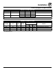
Installation Oven Description & Specifications ratings - HV-100G & HVH-100G Type of gas gas input voltage Phase amps Natural 60,000 BTU/Hr 115 1 10 208/240 1 5 Propane 60,000 BTU/Hr 115 1 10 208/240 1 5 3/4” NPT connector for all U.S.
Installation Utility Connections - Standards and Codes THE INSTALLATION INSTRUCTIONS CONTAINED HEREIN ARE FOR THE USE OF QUALIFIED INSTALLATION AND SERVICE PERSONNEL ONLY. INSTALLATION OR SERVICE BY OTHER THAN QUALIFIED PERSONNEL MAY RESULT IN DAMAGE TO THE OVEN AND/OR INJURY TO THE OPERATOR. U.S.
Installation Oven Location and Ventilation owner’s responsibilities ventilation Installation responsibilities prior to service startup inspection The necessity for a properly designed and installed ventilation system cannot be over emphasized. The ventilation system will allow the unit to function properly while removing unwanted vapors and products of combustion from the operating area. You are entitled to a free start-up inspection service by our factory ASAP.
Installation Leg Attachment leg options attachment 1. Align the threaded stud on one of the front legs to the bolt hole located in the bottom corner of the appliance. Turn the leg clockwise and tighten to the nearest full turn. 2. Align the leg plate holes with the bolt holes. Secure with the two 1/2” bolts provided. 3. Repeat the above steps with the other front leg. If casters are used, install them with the locking casters in the front of the oven. The rear casters do not lock.
Installation Caster Attachment casters for single ovens Profile Casters for double stack ovens 1. Attach the legs as described. 1. Place a level on the floor where the casters are to rest. 2. Pry the adjustable feet out of the legs. 2. Place shims under the low side until it is level. 3. Insert one caster into each leg as shown. Tighten the lock nuts to secure the casters. 3. Mount the shims between the casters and the oven as follows: a. Align the shims and caster holes with the bolt holes.
Installation Stacking 1. Attach the legs or casters to the bottom oven. WARNING!! 2. Place the top oven on the bottom oven. Be sure all four sides are flush. Stacking should be performed by qualified installation personnel only. The ovens are heavy. Take care to use proper tools and techniques when lifting and stacking units. Stacking Bracket 3. Bolt the two ovens together from behind using the stacking brackets.
Installation Plumbing Connections Water Connection Specific water/drain connection for City of Los Angeles NOTE: Must use COLD WATER ONLY. 1. Each drain line from the appliance shall be routed without dips or sags to terminate above the flood level rim of an approved indirect waste receptor. Connect the appliance to quality water via a pressure hose with 3/4” GHT (19mm) couplings. See Figure 6 for connections. A shut off valve is to be provided adjacent to the oven. 2.
Installation Electrical Connections All Models Electric Models NOTE: Electrical connections must be performed by a qualified installer only. A strain relief for the power supply cord is provided. The installer must supply a cord that meets all Local and National installation standards. Before making any electrical connections to these appliances, check that the power supply is adequate for the voltage, amperage, and phase requirements stated on the rating name plate mounted on the appliance.
Installation Gas Connection gas piping Maximum Capacity of Iron Pipe in Cubic Feet of Natural Gas Per Hour A properly sized gas supply system is essential for maximum oven performance. Piping should be sized to provide a supply of gas sufficient to meet the maximum demand of all appliances on the line without loss of pressure at the equipment. (Pressure drop of 0.5 Inch W.C.
Installation Gas Connection pressure regulation and testing Prior to connecting the appliance, gas lines should be thoroughly purged of all metal filings, shavings, pipe dope, and other debris. After connection, the appliance must be checked for correct gas pressure. The gas pressure to the appliance must be rated for each appliance while the burners are on. A sufficient gas pressure must be present at the inlet to satisfy these conditions. Refer to the table below for correct gas pressure. U.S.
Installation Gas Hose Restraint U.S. and Canadian installations If the appliance is mounted on casters, a commercial flexible connector with a minimum of 3/4” (1.9 cm) inside diameter must be used along with a quick connect device. The connector must comply with the Standard for Connectors for Movable Gas Appliances, ANSI Z21.69 or Connectors For Moveable Gas Appliances CAN/CGA6.16 and a quick disconnect device that complies with the Standard for Quick-Disconnect Devices for Use With Gas Fuel, ANSI Z21.
Operation Safety Information What to do in the event of a power failure: The information contained in this section is provided for the use of qualified operating personnel. Qualified operating personnel are those who have carefully read the information contained in this manual, are familiar with the functions of the oven and/or have had previous experience with the operation of the equipment described.
Operation Standard Control NOTE: Not available on HVH-100E and HVH-100G. CONTROLS IDENTIFICATION 1. MODE SELECTOR SWITCH - turns power to the oven on or off. Allows selection of Hydro, Hydro Max, Hot Air, or Cool Down Modes. 1 2. DISPLAY - displays time and temperature information. 3. TEMPERATURE DIAL - used to set desired cooking temperature. 3 4. HEAT LAMP - lights when the oven is calling for heat 2 4 5. TIMER LED - lights when the cook time is displayed 6.
Operation Standard Control TIMER COOKING probe cooking 1. Press the TIMER/PROBE KNOB (8) to select the timer mode. The TIMER LED lights. 1. Press the TIMER/PROBE knob (8) to select the probe setpoint mode. The PROBE SETPOINT LED (7) lights. 2. Turn the MODE SELECTOR Switch (1) to the desired function. 2. Rotate the knob to enter the desired final cook temperature in the display. 3. Set the TEMPERATURE DIAL (3) to the desired cook temperature. 3. Insert the core probe into the product.
Operation MenuSelect™ Control NOTE: Not available on HVH-100E and HVH-100G. Control Description 2 1 1. START/STOP KEY - press to start, cancel or pause the bake HV-100G 2. COOL DOWN KEY - initiates oven cool down cycle 3 3. BAKE MORE KEY - press at the end of a bake cycle to add additional bake time in one minute increments. 4. DISPLAY - displays time or temperature and other information related to oven function and/or programming. 4 5.
Operation MenuSelect™ Control OVEN STARTUP PROGRAMMED COOKING 1. Be sure the shutoff switch and/or circuit breaker switch below the control panel are in the on position. The display flashes OFF PRESS POWER KEY TO START. 1. Turn the DIAL (1) until the name of the product is highlighted. Press the center of the dial to select. The oven preheats to the programmed temperature in the correct cooking mode.
Operation MenuSelect™ Control Oven Shutdown 6. Connect the core probe to the PROBE CONNECTION (19) at the bottom of the control. 1. Press the COOL DOWN KEY (2). The display reads AUTO COOL DOWN ACTUAL TEMP. To speed up the cool down process, open the doors and press the VENT KEY (12) to open the vent. NOTE: Do not connect the probe before the cook mode has been selected. 7. The display gives the actual core probe temperature as well as the oven set temperature. 2.
Operation MenuSelect™ Control PRODUCT programming Entering the Program Mode 4. Rotate the dial to select the desired cooking mode. Choose from Hydro or Hot Air. Press the center of the dial to set the cook mode. 1. Press the PROGRAM KEY (13). If the control is password protected, the display reads ENTER CODE. Use the alpha/numeric keypad to enter the manager passcode 6647, then press the center of the dial to enter the program mode.
Operation MenuSelect™ Control Using the USB Port Programming Oven Setup 1. With the power on, remove the cover of the USB port (20) and insert the USB drive. These menus allow the manager to set up basic oven functions 2. Press the MAINTENANCE KEY (15). 1. Turn the dial to highlight OVEN SETUP. Press the center of the dial to select. 3. Turn the dial to highlight MANAGER PROGRAM. Press the center of the dial to select. 2. Turn the dial to highlight MANAGER PROGRAM.
Operation SmartTouch Touchscreen Control Control Description 1. DISPLAY - displays information related to oven function and/or programming. 2. USB Port and COVER - Use to transfer recipes and data to/from the control 3. CORE PROBE CONNECTION - plug core temperature probe in here when using probe cooking 4. HEAT CUTOFF - used to turn gas on or off (HV-100G & HVH-100G only) 5. CIRCUIT BREAKER - Used to turn power to the unit on or off. 1 manual mode cooking 1.
Operation SmartTouch Touchscreen Control Fan Speed - With the FAN icon highlighted, press the fan speed text (Gentle, Low, High or Turbo). When Turbo is displayed, press the text again to reduce the fans speed to Gentle. Lights - At any time the lights can be turned on or off by toggling the LIGHT icon. 3. Press START Icon to begin cooking. Press Cancel key to stop cooking. Press +1 MIN to add 1 minute to the cook time. Fan Reversal Interval - To adjust the fan reversal time, press the FAN REVERSAL icon.
Operation SmartTouch Touchscreen Control Temp Probe Cooking Time Steam on Demand Hot Air Mode Hydro Mode Fan Speed Fan Reversal Increment Lights Vent Position Figure 12 24
Operation SmartTouch Touchscreen Control Menu mode cooking 1. On a manual screen, press the ESC key to exit the screen. 4. Within the food category, select the desired product you wish to cook. 2. Select the MENU key to cook using the preprogrammed menu items. Figure 15 5. Once selected the control returns to the Menu Cooking screen. Press the START KEY to begin the cook cycle. Figure 13 3. Select the desired food category for your product.
Operation SmartTouch Touchscreen Control shelf cooking 1. Select the SHELF COOKING key. 3. During the cook cycle, individual shelf cook timers will count down as the product is cooked. If you wish to cancel the bake, you can press the STOP ALL key, or you can stop individual shelves. To add time, select +1 MIN key for individual shelves or +1 MIN ALL key to add time to all shelves. Each time the key is pressed, 1 minute of cook time is added. Press STOP again to reset to the original values.
Operation SmartTouch Touchscreen Control editing a menu 1. Select the MENU/EDIT icon to edit the recipes in the menu mode. 3. To edit an existing item, select the item while the EDIT ITEMS key is highlighted. To delete an Item, select the item while the DELETE key is highlighted. To create a new item, select the NEW ? icon while the EDIT key is highlighted. Figure 20 2. Select the EDIT ITEMS icon to edit the menu items.
Operation SmartTouch Touchscreen Control 4. Each recipe is made up of steps containing seven settings - temperature, time, fan, etc. A new step is needed when you desire a different setting within a step. To edit a setting within a particular step, press the icon for that setting. A keypad will appear for you to input your value. To add a step, press the + key icon. To edit a step, press the arrow keys on the bottom left hand corner of the screen to highlight the step you wish to edit.
Operation SmartTouch Touchscreen Control editing a category 1. Select the MENU/EDIT icon to edit the recipes in the menu mode. To delete a category, select the category while the DELETE key is highlighted. To create a new category, select the NEW ? icon while the EDIT key is highlighted. Figure 24 Figure 26 2. Select the EDIT CATEGORIES icon to select which items are in each category. 4. Select what you would like to edit. To edit the name, press the EDIT NAME key.
Operation SmartTouch Touchscreen Control 5. To edit the category icon, press the category icon displayed in the category edit screen. The Select Icon screen is displayed. Select the desired icon. To view more icon options, press the arrow key. 6. To edit items within a category, press the SELECT ITEMS key on the edit category screen. Select the items you would like to appear within the category. When complete, press ESC key to return to the previous menu. Press the DISK icon to save your changes.
Operation SmartTouch Touchscreen Control creating new menu items 5. Program the recipe steps - Each recipe is made up of steps containing seven settings - temperature, time, fan, etc. A new step is needed when you desire a different setting within a step. 1. Select the EDIT ITEMS key. To edit a setting within a particular step, press the icon for that setting. A keypad will appear for you to input your value. To add a step, press the + key icon.
Operation SmartTouch Touchscreen Control creating new categories 1. Select the EDIT CATEGORIES key. 4. Press EDIT NAME. A keyboard will appear. Enter the desired name. Press ENTER when finished to return to the previous screen. 5. Press SELECT ITEMS. Select items to be filed in the new category. Items will be highlighted as they are selected. Press ESC key to return to the previous screen. The disk will be displayed, press to save your changes. 6.
Operation SmartTouch Touchscreen Control transferring recipes using the usb To Store Menu Data to a USB 1. Return to the power screen. 1. Press the STORE MENU DATA to USB key to transfer recipes to the USB. Figure 32 Figure 34 2. Press the TOOLS key. Enter the code 6647 on the keypad. 2. The keyboard screen is displayed. Use to enter desired file name. Press the ENTER key when finished. Figure 33 Figure 35 3. Press the MANAGE MENU DATA key. Insert the USB drive into the Intelliport.
Operation SmartTouch Touchscreen Control 3. The status screen appears to display the download status. The display returns to the previous screen when download is complete. Figure 38 Figure 36 3. The overwrite warning screen appears. Press YES to continue 4. Press the ESC key to exit USB screen. To Retrieve Menu Data from USB 1. Press the GET MENU DATA from USB key to transfer recipes from the USB. Figure 39 4. The status screen appears to display the upload status.
Operation SmartTouch Touchscreen Control cool down 1. To cool down the unit, press the COOL DOWN icon. 2. The oven will toggle between cooling and open door in yellow until the oven is cool. Once cool, the oven will go to standby. NOTE: If the oven is shut down with the circuit breaker switch at the bottom of the front panel, the display will return to the power screen. Select your option to begin.
Maintenance Spray Bottle Operating Procedure NOTE: Only use a commercial oven cleaner/degreaser with the spray bottle. DO NOT use chemicals that are not intended as oven cleaners. See chemical manufacturer’s information for intended use. WARNING!! Protective clothing and eyewear should be worn while using cleaning agents. 1. Unscrew the sprayer head and fill the container to the MAX mark. Screw the head assembly on firmly to ensure an airtight seal. The liquid must be clean and free from foreign matter.
Maintenance Cleaning and Preventive Maintenance CLEANING THE INTERIOR On stainless interiors, deposits of baked on splatter, oil, grease or light discoloration may be removed with a good non toxic industrial stainless steel cleaner. Apply cleaners when the oven is cold and always rub with the grain of the metal. The racks, rack supports and the blower wheel may be cleaned in the oven or by removing them from the oven and soaking them in a solution of ammonia and water.
Maintenance Cleaning and Preventive Maintenance Oven Weekly Cleaning 5. Thoroughly spray cleaner onto the fan and heat source. Close the door to allow the cleaner to work. In addition to the daily cleaning, it is necessasry to clean behind the fan guard of this oven on a weekly basis. This is necessary for proper functioning of the oven. Scale will build up on the fan and heat source leading to a less efficient oven. 6. After ten minutes, rinse the cleaner off.