KLS-20G, KLS-40G and KLS-60G GAS FIRED TRI-LEG STATIONARY KETTLE INSTALLATION – OPERATION – MAINTENANCE BLODGETT OVEN COMPANY 1 www.blodgett.
IMPORTANT NOTES FOR INSTALLATION AND OPERATION It is recommended that this manual be read thoroughly and that all instructions be followed carefully. This is the safety alert symbol. It is used to alert you to potential personal injury hazards. Obey all safety messages that follow this symbol to avoid possible injury or death. FOR YOUR SAFETY: Do not store or use gasoline or other flammable vapours or liquids in the vicinity of this or any other appliance.
TABLE OF CONTENTS DESCRIPTION PAGE Important Notes for Installation and Operation ................................................................. 2 1.0 Service Connections ................................................................................................. 4 2.0 Installation ................................................................................................................. 5 3.0 Performance Check .................................................................................
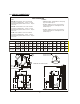
1.0 SERVICE CONNECTIONS UTILITY INFORMATION: ELECTRIC: 1 STANDARD: 115/60/1 - furnished with 6 ft. cord w/3-prong plug. Total maximum amps 2.0. GAS: KLS-20G-Total 100,000 BTU. One 1" male connection (for location, see drawing below.) 1 Natural 1 Propane Required operating pressure: Natural Gas 4" W.C.; Propane Gas 10" W.C 1 OPTIONAL: 208/60/1 or for use on 3 (190 to 219 volts) supply must be wired to unit - see drawing below. Total maximum amps 1.0. KLS-40G - Total 100,000 BTU. One 1" male connection.
2.0 INSTALLATION INSTALLATION CODES AND STANDARDS Installation must conform with local codes, or in the absence of local codes, with the National Fuel Gas Code, ANSI Z223.1/NFPA 54, or the Natural Gas and Propane Installation Code, CSA B149.1, as applicable. 1. The appliance and its individual shut off valve must be disconnected from the gas supply piping system during any pressure testing of that system at pressures in excess of ½ psi (3.5 kPa). 2.
2.0 INSTALLATION (Continued) TO INSTALL 1. Uncrate carefully. Report any hidden freight damage to the freight company immediately. 2. Set the unit in place. Be certain to maintain minimum clearances as stated above. 3. To level the unit use a spirit level in all directions on the top of the kettle (lid up). A. Units with legs - adjust the bottom foot on each leg to overcome an uneven floor. B. Units with casters - loosen the locking nuts, turn casters in or out as required and tighten locking nuts. 4.
2.0 INSTALLATION (Continued) Purge the supply line to clean out any dust, dirt, or other foreign matter before connecting the line to the unit. It is recommended that an individual manual shut off valve be installed in the gas supply line to the unit. Use pipe joint compound which is suitable for use with LP gas on all threaded connections. Test pipe connections thoroughly for gas leaks. WARNING: All connections must be checked for leaks, after the unit has been put in operation.
2.0 INSTALLATION (Continued) WARNING: Do not connect the appliance to the electrical supply until after the gas connection has been made. WARNING: ELECTRICAL GROUNDING INSTRUCTIONS This appliance is equipped with a three-prong (grounding) plug for your protection against shock hazard and should be plugged directly into a properly grounded three-prong receptacle. Do not cut or remove the grounding prong from this plug. (120V units only).
3.0 PERFORMANCE CHECK The following items should be checked before or within the first 30 days of operation by a qualified service technician. 1.0 Verify correct gas type. 2.0 Verify correct voltage, cycle and phase. 3.0 Gas pressure. 4.0 Internal gas connections. 5.0 Internal electrical connections. 6.0 Pilots - adjustment and ignition. 7.0 Burners - adjustment and ignition. 8.0 Thermostat - cycle for operation check. 9.0 Supply valve - check for operation. 10.
4.0 OPERATION Contact the factory, the factory representative or a local service company to perform maintenance and repairs should the appliance malfunction. WARNING: In the event of main burner ignition failure, a 5 minute purge period must be observed prior to re-establishing ignition source. WARNING: In the event you smell gas, shut down equipment at the main shut off valve and contact the local gas company or gas supplier for service.
4.0 OPERATION (Continued) 7. When the pilot is ignited the spark igniter will automatically stop and within 15 seconds main burner gas will come on. If ignition does not occur, after a total of ninety seconds, the unit will lockout, shutting off all gas although the spark igniter will continue to spark.
4.0 OPERATION (Continued) SPARK IGNITER FAILURE: In the event the spark igniter module fails the unit may still be operated by carefully following these instructions. 1. Turn thermostat to OFF position; completely counter clockwise. 2. Turn power switch to OFF position. 3. WAIT A MINIMUM OF 5 MINUTES BEFORE PROCEEDING. 4. Turn dial on combination control to ON position (if not already on). 5. Turn power switch to ON position. 6.
4.0 OPERATION (Continued) FRONT PANEL CONTROLS: 1. Power Switch This switch turns the main power to the unit on and off. It must be turned on to heat the kettle. It should be turned off when the kettle will not be in use for long periods. 2. (Red) Cooking Light This light is on whenever the main burner gas is on. On units with standing pilots this light may be on without the burners being on if the pilot is extinguished. See lighting instructions. 3.
4.0 OPERATION (Continued) DAILY OPERATION Daily operation should consist of turning on the power switch and setting the thermostat for the desired temperature. It is recommended the kettle be preheated prior to use. Milk or egg based products should be placed in the kettle before heating, however, to prevent sticking. The kettle is preheated when the cooking light goes off the first time.
END USER TIPS: (Continued) Bring milk and egg products slowly up to temperature in a cold kettle to prevent product adhering to the sides. When planning actual cooking capacity, allow room at top for stirring without spilling. When preparing puddings from a mix, place the powder in a cold kettle, add a small amount of the liquid, and stir to form a thin paste. Turn on the kettle and add the remainder of the liquid. Continue as per recipe instructions.
5.0 MAINTENANCE Contact the factory, the factory representative or a local service company to perform maintenance and repairs. WARNING: Disconnect the power supply to the appliance before cleaning or servicing. Daily: 1. Wash exposed cleanable areas. Monthly: 1. Clean around burner air mixers, louvered panels and pilots if grease or lint have accumulated. TWICE A YEAR: (minimum) Have an authorized service person clean and adjust the unit for maximum performance.
5.0 MAINTENANCE (Continued) CLEANING INSTRUCTIONS WARNING: Disconnect the power supply to the appliance before cleaning or servicing. WARNING: Never spray water into electric controls or components! CAUTION: The equipment and its parts are hot. Use care when operating, cleaning and servicing. CAUTION: Do not use cleaning agents that are corrosive. Your kettle should be cleaned immediately after each use or when cooking a different product.
5.0 MAINTENANCE (Continued) CLEANING INSTRUCTIONS (Continued) DRAW-OFF VALVE CLEANING 1. If equipped with a tangent draw-off valve, turn the large hex nut on the draw-off valve counter clockwise until it is completely disengaged from the threads. Grasp the valve knob and slowly pull out the valve stem and disk. Do not allow the disk to come in contact with hard surfaces as it can be damaged and cause valve leakage. Wash the valve stem, disk and handle.
5.0 MAINTENANCE (Continued) CLEANING INSTRUCTIONS (Continued) WHAT TO DO IF SURFACE RUST APPEARS Metal utensils should never be used as they will scratch the surface of the equipment and rust may begin to form. To remove surface accumulation of rust from the inadvertent use of such utensils, the following procedure may be used. CAUTION: Improper use of this procedure may damage your appliance! 1.
5.0 MAINTENANCE (Continued) CLEANING INSTRUCTIONS (Continued) STAINLESS STEEL (Continued) Soil and burn deposits which do not respond to the above procedure can usually be removed by rubbing the surface with SCOTCH-BRITE™ scouring pads or STAINLESS scouring pads. DO NOT USE ORDINARY STEEL WOOL as any particles left on the surface will rust and further spoil the appearance of the finish. NEVER USE A WIRE BRUSH, STEEL SCOURING PADS (EXCEPT STAINLESS), SCRAPER, FILE OR OTHER STEEL TOOLS.
SAFETY VALVE MAINTENANCE AND TESTING CAUTION! Under normal operating conditions a “try lever test” should be performed every two months. Under severe service conditions, or if corrosion and/or deposits are noticed within the valve body, testing must be performed more often. A “try lever test” should also be performed at the end of any non-service period. CAUTION! Hot, high pressure fluid may be discharged from body drain and vent during “try lever” test. Care must be taken to avoid any bodily contact.
6.0 SERVICE WARNING: Disconnect unit from power supply before cleaning or servicing appliance. GENERAL When any difficulty arises always check that the unit has been connected to the gas supply type and voltage for which it was supplied. This can be done by examining the serial plate on the lower right side of the unit. It will list the gas type and voltage for which the unit was manufactured. Wiring diagrams for the unit are located in a small envelope affixed to the rear side of the front control panel.
6.0 SERVICE (Continued) The front burner shield should be removed to see the pilot. The pilot should be adjusted as follows: Adjust the pilot burner flame The pilot flame should envelop 3/8 to ½ inch [10 to 13 mm] of the igniter-sensor tip. Refer to Figure 2. To adjust the pilot flame: 1. Remove the pilot adjustment cover screw. Refer to Figure 1. 2. Turn the inner adjustment screw clockwise to decrease or counter clockwise to increase the pilot flame. Figure 2 - Proper flame adjustment 3.
6.0 SERVICE (Continued) ADJUSTMENTS To check the manifold pressure a pressure gauge (manometer) must be connected to the 1/8" NPT pressure tap on the gas manifold. With the gas off, connect your pressure indicating instrument to the manifold with a fitting appropriate for your instrument. 1. Turn the unit on; with main burners on, read the manifold pressure. The pressure should be 4 inches water column (W.C.) 2 inches W.C. for natural gas or 10 inches W.C. for propane gas.
6.0 SERVICE (Continued) PRESSURE SWITCH (Continued) 1. Pressure relief valve opening, especially on preheat from a cold start to 275°F (135°C) (pressure switch set too high). 2. Burners are being shut down by pressure switch, not the thermostat. (Pressure switch set too low.) The pressure switch is preset for proper operation from the factory. It is adjusted to the maximum pressure, however not high enough to cause the pressure relief valve to open.
6.0 SERVICE (Continued) ADDING WATER It may be necessary to replenish water in the jacket when the low water indicator comes on. Do so as follows: • Unit should be completely cold and off. • For reference, the total amount of distilled water contained in each unit, and amount to be added in a low water condition is listed below: Model Total Amount of Distilled Water Amount of Water to be Added in a Low Water Condition KLS-20G 6 Gallons 135 fl. oz. (4 L) KLS-40G 9 Gallons 236 fl. oz.
6.0 CONVERTING BETWEEN NATURAL AND PROPANE GAS WARNING: Fire or explosion hazard can cause property damage, severe injury, or death. 1. Do not attempt to use a gas control set for natural gas on propane gas or gas control set for LP gas on natural gas. 2. When making conversion, main and pilot burner orifices MUST be changed to meet appliance manufacturer’s specifications. Standard- or slow-opening gas controls may be converted from one gas to another.
6.0 SERVICE (Continued) CONVERTING BETWEEN NATURAL AND PROPANE GAS (Continued) Figure 1 Top view of gas control. Figure 2 Installation of conversion kit in regulated gas control.
TROUBLESHOOTING PROBLEM LOOK FOR Unit will not come on - Power switch is off. - Unit not plugged in. - Main power supply off. - Bad electronic module. - Bad low water control. - Bad spark igniter. - Bad intermittent pilot burner. - Fuse in unit blown. Unit will turn on electrically but will not heat - Lockout has occurred. - Thermostat not on. - Gas control valve off. - Main gas supply off. - Low water. - Bad thermostat. - Bad pressure switch. - Bad gas control valve. - Bad spark igniter.
TROUBLESHOOTING: PROBLEM LOOK FOR Excessive flame rollout on ignition, carboning - Natural gas unit on propane. - Excessive gas pressure. - Incorrect orifice size. - Faulty regulator in gas control. Unit slow to preheat and slow to recover - Propane gas on natural. - Low gas pressure. - Incorrect orifice sizes. - Loss of vacuum. - Faulty regulator in gas control. Unit continuously locks out - Pilot gas adjusted too low. - Excessive draft condition.
APPENDIX ‘A’ MATERIAL SAFETY DATA SHEET PREPARATION INFORMATION: Prepared for use in Canada by: E H & S Product Regulatory Management Department DOW CHEMICAL CANADA INC. P.O. Box 1012 Sarnia, Ontario, N7T 7K7 (800) 331-6451 1.
HAZARDS IDENTIFICATION EMERGENCY OVERVIEW Clear yellow liquid. Odourless. Avoid temperatures above 450°F, 232°C. POTENTIAL HEALTH EFFECTS (See Section 11 for toxicological data.) EYE: May cause slight transient (temporary) eye irritation. Corneal injury is unlikely. Mists may cause eye irritation. SKIN CONTACT: Prolonged contact is essentially nonirritating to skin. A single prolonged exposure is not likely to result in the material being absorbed through skin in harmful amounts.
4. FIRST AID EYES: Flush eyes with plenty of water. SKIN: Wash off in flowing water or shower. INGESTION: No adverse effects anticipated by this route of exposure incidental to proper industrial handling. INHALATION: Remove to fresh air if effects occur. Consult a physician. NOTE TO PHYSICIAN: No specific antidote. Supportive care. Treatment based on judgment of the physician in response to reactions of the patient. 5.
MEDIA TO BE AVOIDED: Do not use direct water stream. FIRE FIGHTING INSTRUCTIONS: Keep people away. Isolate fire area and deny unnecessary entry. Burning liquids may be moved by flushing with water to protect personnel and minimize property damage. Burning liquids may be extinguished by dilution with water. Do not use direct water stream. May spread fire. Fight fire from protected location or safe distance. Consider use of unmanned hose holder or monitor nozzles.
SKIN PROTECTION: Use gloves impervious to this material. RESPIRATORY PROTECTION: Atmospheric levels should be maintained below the exposure guideline. When respiratory protection is required for certain operations, use an approved airpurifying respirator. In misty atmospheres, use an approved mist respirator. EXPOSURE GUIDELINES: Propylene glycol: AIHA WEEL is 50 ppm total, 10 mg/m3 aerosol only. 9.
MUTAGENICITY: In vitro mutagenicity studies were negative. Animal mutagenicity studies were negative. ECOLOGICAL INFORMATION (For detailed Ecological data, write or call the address or nonemergency number shown in Section 1.) ENVIRONMENTAL FATE MOVEMENT & PARTITIONING: Based largely or completely on data for major component(s). Bioconcentration potential is low (BCF less than 100 or Log Pow less than 3). Potential for mobility in soil is very high (Koc between 0 and 50).
14. TRANSPORT INFORMATION DEPARTMENT OF TRANSPORTATION (D.O.T.): For D.O.T. regulatory information, if required, consult transportation regulations, product shipping papers, or contact your Dow representative. CANADIAN TDG INFORMATION: For TDG regulatory information, if required, consult transportation regulations, product shipping papers, or your Dow representative. * or (R) indicates a trademark of The Dow Chemical Company. 15.
U.S. REGULATIONS SARA 313 INFORMATION: To the best of our knowledge, this product contains no chemical subject to SARA Title III Section 313 supplier notification requirements. SARA HAZARD CATEGORY: This product has been reviewed according to the EPA “Hazard Categories” promulgated under Sections 311 and 312 of the Superfund Amendment and Reauthorization Act of 1986 (SARA Title III) and is considered, under applicable definitions, to meet the following categories: Not to have met any hazard category.
CANADIAN REGULATIONS WHMIS INFORMATION: The Canadian Workplace Hazardous Materials Information System (WHMIS) Classification for this product is: This product is not a “Controlled Product” under WHMIS. CANADIAN ENVIRONMENTAL PROTECTION ACT (CEPA) This product contains one or more substances which are not listed on the Canadian Domestic Substances List (DSL). Contact your Dow representative for more information. 16. OTHER INFORMATION MSDS STATUS: Revised to 16 section format.