SB-6SC, SB-10SC and SB-16SC CONVECTION STEAMER ON A STEAM COIL BOILER BASE INSTALLATION – OPERATION – MAINTENANCE BLODGETT OVEN COMPANY www.blodgett.
IMPORTANT NOTES FOR INSTALLATION AND OPERATION It is recommended that this manual be read thoroughly and that all instructions be followed carefully. This is the safety alert symbol. It is used to alert you to potential personal injury hazards. Obey all safety messages that follow this symbol to avoid possible injury or death. WARNING: Improper installation, operation, adjustment, alteration, service or maintenance can cause property damage, injury or death.
TABLE OF CONTENTS DESCRIPTION PAGE Important Notes....................................................................................................... 2 Service Connections ............................................................................................... 4 Introduction ............................................................................................................. 5 1.0 Installation Instructions .................................................................................
SERVICE CONNECTIONS ELECTRICAL CONNECTION: 1/2" conduit connection to controls. 120VAC-60Hz-1PH2 AMPS per compartment or to be as specified on data plate. DRAIN: 2"IPS piped to open floor drain. No Solid Connection. COLD WATER: 3/8" O.D. tubing at 25-50 PSI(170-345 kPa). STEAM SUPPLY: 3/4" female pipe connection for 25-50 PSI(170-345 kPa). S WATER QUALITY STATEMENT Water quality is the major factor affecting the performance of your appliance.
INTRODUCTION DESCRIPTION Models SB-6SC and SB-10SC convection steamers mounted on 24” cabinet base and a steam coil boiler. An optional 36” cabinet is available for these models. Model SB-16SC convection steamers mounted on 36” cabinet base and a steam coil boiler. All bases are designed to ASME Code and approved as a steam boiler restricted to operation at pressure not to exceed 15 psi. SB-6SC steamer has a pan capacity of 6 (2-1/2") pans. SB-10SC has a pan capacity of 10 (2-1/2") pans.
1.0 INSTALLATION INSTRUCTIONS UNPACKING Immediately after unpacking, check for possible shipping damage. If the appliance is found to be damaged, save the packaging material and contact the carrier within 15 days of delivery. Before installing, verify the electrical rating agrees with the specification on the rating plate. LOCATION Position the appliance in its installation location. Check that there are sufficient clearances to service the controls, door swing, etc.
1.0 INSTALLATION INSTRUCTIONS (continued) Ideally an exhaust system should be located directly above the appliance to exhaust steam and heat generated by the appliance. 1. Set the unit in place and level using a spirit level. 2. Ascertain that a floor drain (open gap) is convenient to the appliance drain. 3. Mark hole locations on floor through anchoring holes provided in flanged adjustable feet. 4. Remove appliance and drill holes in locations marked on floor and insert proper anchoring devices. 5.
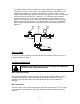
2.0 INFORMATION TO STEAM FITTER Assuming availability of 30 psi supply steam pressure immediately to the appliance, then pipe sizes of ½" or 3/4" or 1" will deliver respectively 90, 165 or 385 lbs. of steam per hour to the appliance Heat Exchanger. From the foregoing to use ½" pipe line would most likely prove inadequate. An extremely important consideration is the pressure drop that will occur through the steam supply line from its point of origin to the appliance.
It is suggested that, wherever possible, the steam supply line to the appliance is a separate line from the steam source. If the appliance must be supplied from a line supplying other appliances, the pipe sizes and pressure will have to be verified. Further, during idle periods, when the steam in the supply line is not in use, water will form from condensed steam in the supply line. It is advisable to prevent water pockets from forming in the steam line and impeding the steam flow when it is required.
3.0 OPERATING INSTRUCTIONS START UP INSTRUCTIONS Turn on water and steam supply to appliance. Open cabinet door and turn on Power Switch. Pilot light will come ON and steam generating will begin. In approximately 20 minutes, sufficient amount of pressurized steam will have been generated in the heat exchanger. The appliance is now ready for steam generation. SHUT DOWN Turn off power switch, open manual drain valve. If unit is equipped with automatic blowdown valve, it will open and drain exchanger.
3.0 OPERATING INSTRUCTIONS (Continued) CAUTION: An obstructed drain can cause personal injury or property damage. Frequently check that the compartment drain and plumbing is free of all obstructions. Never place food containers, food or food portion bags in the cooking compartment in such a way that the compartment drain becomes obstructed. Each compartment is equipped with a removable drain screen. Frequently check the drain screen for accumulation of food particles.
4.0 PERIODIC MAINTENANCE CAUTION: Protect yourself. When flushing control, hot water and steam will flow out of the drain. Be sure to flush your boiler water level control daily. Failure to follow this procedure can cause the control to malfunction resulting in serious boiler damage. The Boiler Water Level Control installed on your boiler requires periodic maintenance. As boiler water circulates into the float chamber, sand, scale and other sediment may be deposited in the float chamber.
Continue draining water for about fifteen (15) seconds, from control until water is clean. Manually close valve. Recheck gauge glass. If water level has dropped significantly, wait for the boiler to restore water level and pressure and repeat if necessary. 1. Water level control should be opened daily to blowdown sediment and scalant. 2. Observe that the water in gauge glass is clean and clear. Extreme murkiness in water indicates inadequate water quality. 3.
5.0 CLEANING INSTRUCTIONS Never spray water into electric controls. CAUTION: Do not use cleaning agents that are corrosive. CAUTION: Live steam and accumulated hot water in the compartment may be released when the door is opened. 1. Keep exposed cleanable areas of unit clean at all times. 2. Thoroughly wash oven cavities, door liners, and pan racks at the end of each day or as required with a mild detergent and water to prevent bacterial growth and odours. 3.
5.0 CLEANING INSTRUCTIONS (Continued) DESCALING BOILER CAUTION: Improper use of this procedure may damage your appliance! 1. With Generator tank empty, close manual blowdown valve. If appliance is equipped with Automatic Blowdown, turn water supply OFF to appliance. Turn power switch ON, this will energize and close blowdown valve. 2. For appliance on 24" Cabinet, remove union fitting at connection to base of water level control and generator tank. For appliance on 36", 48" etc.
6.0 TROUBLESHOOTING NOTICE: Contact the factory, the factory representative or local service company to perform maintenance and repairs. Refer to warranty terms. DOOR LEAKS 1. Check for damage to door gasket. WATER ACCUMULATES IN THE COMPARTMENT 1. Compartment drain screen clogged. Remove and clean thoroughly and then replace. WATER NOT BEING SUPPLIED TO HEAT EXCHANGER 1. Water supply is “OFF”. 2. Defective water fill solenoid. 3. Water level control clogged or defective, unable to operate fill valve. 4.
TO CALIBRATE PRESSURE SWITCHES NOTE: Pressure switches are factory set. Calibration is only required if pressure switches are replaced or if adjustment is required. Pressure switch range is from 1 to 15 psi. Adjust all settings to maximum on high signal adjustment screw on pressure switches. Adjust in the following sequence: - High limit pressure switch. - Override pressure switch. - Operating pressure switch. - Turning screw clockwise to increase, counterclockwise to decrease pressure.