SC-E Series KTT-E Series ELECTRIC TABLE TOP TILTING ELECTRIC ATMOSPHERIC STEAMER ONKETTLE CABINET BASE INSTALLATION INSTALLATION–- OPERATION OPERATION – - MAINTENANCE BLODGETT OVEN COMPANY BLODGETT OVEN COMPANY www.blodgett.com www.blodgett.
THIS MANUAL MUST BE RETAINED FOR FUTURE REFERENCE. READ, UNDERSTAND AND FOLLOW THE INSTRUCTIONS AND WARNINGS CONTAINED IN THIS MANUAL. FOR YOUR SAFETY Do not store or use gasoline or other flammable vapors and liquids in the vicinity of this or any other appliance. WARNING Improper installation, adjustment, alteration, service or maintenance can cause property damage, injury or death. Read the installation, operating and maintenance instructions thoroughly before installing or servicing this equipment.
IMPORTANT - READ FIRST - IMPORTANT WARNING: THE UNIT MUST BE INSTALLED BY PERSONNEL QUALIFIED TO WORK WITH ELECTRICITY AND PLUMBING. IMPROPER INSTALLATION CAN CAUSE INJURY TO PERSONNEL AND/OR DAMAGE TO THE EQUIPMENT. THE UNIT MUST BE INSTALLED IN ACCORDANCE WITH APPLICABLE CODES. NOTICE: DO NOT BLOCK THE RIGHT SIDE VENTS, AND DO NOT INSTALL WITHIN 12 INCHES OF A HEAT SOURCE SUCH AS A BRAISING PAN, DEEP FRYER, CHAR BROILER OR KETTLE.
IMPORTANT - READ FIRST - IMPORTANT WARNING: USE OF ANY REPLACEMENT PARTS OTHER THAN THOSE SUPPLIED BY THE MANUFACTURER OR THEIR AUTHORIZED DISTRIBUTOR VOIDS ALL WARRANTIES AND CAN CAUSE BODILY INJURY TO THE OPERATOR AND DAMAGE THE EQUIPMENT. SERVICE PERFORMED BY OTHER THAN FACTORYAUTHORIZED PERSONNEL WILL VOID ALL WARRANTIES. WARNING: HIGH VOLTAGE EXISTS INSIDE CONTROL COMPARTMENTS. DISCONNECT FROM BRANCH BEFORE SERVICING. FAILURE TO DO SO CAN RESULT IN SERIOUS INJURY OR DEATH.
Table of Contents Important Operator Warnings ....................................................page 1-2 References.................................................................................... page 3 Equipment Description.................................................................. page 4 Water Quality and Treatment .......................................................... page 5 Inspection and Unpacking ............................................................ page 6 Installation ........
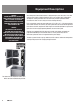
Equipment Description WARNING BEFORE REMOVING ANY PARTITION OR PANEL, TURN OFF THE ELECTRICAL POWER AND LET THE FAN STOP ROTATING. BEFORE WORKING ON ANY ELECTRICAL COMPONENT, DISCONNECT THE POWER SOURCE FROM THE UNIT. WARNING THE UNIT MUST BE INSTALLED BY PERSONNEL WHO ARE QUALIFIED TO WORK WITH ELECTRICITY AND PLUMBING. IMPROPER INSTALLATION CAN CAUSE INJURY TO PERSONNEL AND/OR DAMAGE TO THE EQUIPMENT. THE UNIT MUST BE INSTALLED IN ACCORDANCE WITH APPLICABLE CODES.
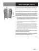
Water Quality & Treatment It is essential to supply the steam generator with water that will not form scale. Even though the steam generator/boiler is engineered to minimize scale formation, scale development depends on the hardness of your water and the number of hours you operate the equipment each day. Most water supplies contain minerals which form scale. It is this scale which could lead to an early component failure. Your local water utility can tell you about the minerals in your water.
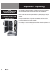
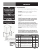
Inspection & Unpacking CAUTION SHIPPING STRAPS ARE UNDER TENSION AND CAN SNAP BACK WHEN CUT. CAUTION THIS UNIT WEIGHS 550 POUNDS. GET HELP AS NEEDED AND USE MATERIAL HANDLING EQUIPMENT TO MOVE IT. Your steamer will be delivered completely assembled in a heavy shipping carton and attached to a skid. On receipt, inspect the carton carefully for exterior damage. Carefully cut the straps around the carton and detach the sides of the carton from the skid. Be careful to avoid personal injury.
Installation WARNING THE UNIT MUST BE INSTALLED BY PERSONNEL WHO ARE QUALIFIED TO WORK WITH ELECTRICITY AND PLUMBING. IMPROPER INSTALLATION CAN CAUSE INJURY TO PERSONNEL AND/OR DAMAGE TO THE EQUIPMENT. THE UNIT MUST BE INSTALLED IN ACCORDANCE WITH APPLICABLE CODES. CAUTION DO NOT INSTALL THE UNIT WITH THE RIGHT SIDE VENTS BLOCKED OR WITHIN 12 INCHES OF A HEAT SOURCE (LIKE A BRAISING PAN, DEEP FRYER, CHAR BROILER, OR KETTLE). TO AVOID DRAIN PROBLEMS, LEVEL THE UNIT FRONT TO BACK.
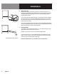
Installation B. Water Connection Install a check valve to prevent back flow in the incoming cold water line, as required by local plumbing codes. Water pressure in the line should be between 30 and 60 PSIG (210 and 420 kPa). If pressure is above 60 PSIG, a pressure regulator will be needed. A ¾ inch NH connector (garden hose type) is used to attach the water supply to the water inlet valve. The minimum water feed line diameter is ½ inch (13mm). Use a washer in the hose connection.
Operation WARNING ALL POTENTIAL USERS OF THE EQUIPMENT SHOULD BE TRAINED IN SAFE AND CORRECT OPERATING PROCEDURES. NO ATTEMPT SHOULD BE MADE TO OPERATE THIS EQUIPMENT DURING A POWER FAILURE. WARNING WHEN YOU OPEN THE DOOR, STAY AWAY FROM THE STEAM COMING OUT OF THE UNIT. THE STEAM CAN CAUSE BURNS. NOTE: Before the steamer can be operated as described in this section, the pilot burner flame must be established.
Operation B. Steamer Timer Operating Procedure 1. Press the ON switch/pad for the steamer. The steam generator will fill, and heat until the READY light comes on. (Aprox. 10 minutes.) 2. Load food into pans in uniform layers. Pans should be filled to about the same levels, and should be even on top. 3. Open the door and slide the pans onto the supports. If you will only be steaming one pan, put it in the middle position. 4. Close the door.
Cleaning WARNING DISCONNECT THE POWER SUPPLY BEFORE CLEANING THE OUTSIDE OF THE STEAMER. KEEP WATER AND CLEANING SOLUTIONS OUT OF CONTROLS AND ELECTRICAL COMPONENTS. NEVER HOSE OR STEAM CLEAN ANY PART OF THE UNIT. To keep your steamer in proper working order, use the following procedure to clean the unit. This regular cleaning will reduce the effort required to clean the steam generators and cavities. A. Suggested Tools 1. Mild detergent 2. Stainless steel exterior cleaner such as Zepper® 3.
Cleaning CAUTION NEVER LEAVE A CHLORINE SANITIZER IN CONTACT WITH STAINLESS STEEL SURFACES FOR LONGER THAN 30 MINUTES. LONGER CONTACT CAN CAUSE CORROSION. DELIMING STEPS (Use Touch Pad): STEP 1 Press ON/OFF to turn steamer off. Open door. STEP 2 Let cavity cool for 5 minutes or longer. While cool, wipe out cavity. Close door.
Maintenance NOTE THE UNIT CONTAINS NO FUSES THAT SHOULD BE REPLACED BY THE OPERATOR. The steamer is designed for minimum maintenance, and no user adjustments should be necessary. Certain parts may need replacement after prolonged use. If there is a need for service, only authorized representatives should perform the work. Always supply water with a low mineral count that meets the standards outlined in the Water Conditioning section of this manual.
Troubleshooting This steamer is designed to operate smoothly and efficiently if properly maintained. However, the following is a list of checks to make in the event of a problem. Wiring diagrams are furnished inside the service panel. If an item on the check list is marked with (X), it means that the work should be done by a factory-authorized service representative. SYMPTOM WHO Steam generator does not fill with water. User a. Is the ON switch depressed? b. Is the water supply connected? c.
Parts List OM-SC-E 15
Parts List 16 OM-SC-E
Parts List OM-SC-E 17
Parts List Key Description Part # Key Description Part # 1 TRANSFORMER 20VA 119815 x TOP PANEL 143116 2 CAPACITOR, 3MF 096813 x FRONT PANEL OVERLAY 170161 3 TRANSFORMER 208/240V PRIMARY/24V SECONDARY, 75VA 121716 x DOOR LATCH PIN 078914 x DOOR PIN LOCK NUT 003823 4 CONTACTOR 148102 x CAVITY FAN 096790 5 FUSEHOLDER 096809 x GENERATOR ASSEMBLY 141481 6 FUSE 071489 x LEFT PAN RACK 094148 7 GROUND TERMINAL 106412 x DOOR HANDLE 070123 8 TERMINAL BLOCK 002577
Electrical Schematic OM-SC-E 19
Service Log Model No: Purchased From: Serial No: Location: Date Purchased: Date Installed: Purchase Order No: For Service Call: Date 20 OM-SC-E Maintenance Performed Performed By
OM-SC-E 21
BLODGETT OVEN COMPANY www.blodgett.