Over The Range Convection Microwave Oven Installation Manual BOTR30100SS BOTR30100B EN FR
Please read this manual first! Dear Customers! Thank you for preferring a Blomberg product. We hope that you get the best results from your product which has been manufactured with high quality and state-of-the-art technology. Therefore, please read this entire user manual and all other accompanying documents carefully before using the product and keep it as a reference for future use. If you handover the product to someone else, give the user manual as well.
CONTENTS 1 Important instructions 4 1.1 General safety............................................................ 4 1.1.1 Electrical safety......................................................5 2 Your over the range convection microwave oven 6 2.1 Overview...................................................................... 6 2.2 Technical data........................................................... 6 3 Mounting space 7 4 External exhaust 8 4.1 Installing hood exhaust.........................
1 Important instructions 1.1 General safety C Read and save these instructions A WARNING: To reduce the risk of fire, electric shock, or injury to persons, always exercise basic safety precautions, including the following: Doing so will: • make installation easier. • help you in the future if you have questions. • help if you have an electrical inspection. Call your dealer when you have questions or need service. When you call, you will need the microwave model and serial numbers.
1 Important instructions The power cord of this appliance is equipped with a three-prong (grounding) plug which mates with a standard three-prong (grounding) wall receptacle to minimize the possibility of electric shock hazard from this appliance. Do not, under any circumstances, cut, deform or remove any of the prongs from the power cord. Do not use with an extension cord. 1.1.1 Electrical safety Product rating is 120 volts AC, 60 Hertz, 15 amps and 1550 watts.
2 Your over the range convection microwave oven 2.1 Overview A B C 2.2 Technical data Product Dimensions Cutout Dimensions A-Height 16.4 ˝ (41.7 cm) Height (Min.) 16.75 ˝ (42.5 cm) B-Width 29.9 ˝ (75.9 cm) Height (Max.) 17.0 ˝ (43.2 cm) C-Depth 15.0 ˝ (38.2 cm) Width (Min.) 30.0 ˝ (76.2 cm) Depth (Min.) 12.0 ˝ (30.5 cm) Depth (Max.) 14.0 ˝ (35.
3 Mounting space Bottom Edge of Cabinet Needs to be 30 (76.2 cm) or More from the Cooking Surface [12“ (30.5 cm) min.] 163⁄ 4 “ (42.5 cm) 30“ (76.2 cm) 30“ (76.2 cm) min. 2“ (5.1 cm) Backsplash 66 (167.6 cm) or More from the Floor to the Top of the Microwave C C C The space between the cabinets must be 30“ (76.2 cm)wide and free of obstructions. If you are going to vent your microwave oven to the outside, see Hood Exhaust Section for exhaust duct preparation.
4 External exhaust 4.1 Installing hood exhaust C Read these instructions only if you plan to vent your exhaust to the outside. If you plan to recirculate the air back into the room, proceed to title 5 4.1.1 Outside top exhaust (example only) The following chart describes an example of one possible ductwork installation. Equivalent Length x Number used = Equivalent Roof Cap 24 Ft. (7.3 m) x (1) = 24 Ft. (7.3 m) 12 Ft. (3.6 m) Straight Duct (6”/15.2 cm Round) 12 Ft. (3.6 m) x (1) = 12 Ft.
4 External exhaust 4.1.2 Outside back exhaust (example only) The following chart describes an example of one possible ductwork installation. Equivalent Length x Number = Equivalent Length Wall Cap 40 Ft. (12.2 m) x (1) = 40 Ft. (12.2 m) 3 Ft. Straight Duct (31⁄4” x 10”/8.2 x 25.4 cm Rectangular) 3 Ft. (0.9 m) x (1) = 3 Ft. (0.9 m) 90° Elbow 10 Ft. (3 m) x (2) = 20 Ft. (3 m) Total Length = 63 Ft. (19.
4 External exhaust 4.1.4 Maximum duct length For satisfactory air movement, the total duct length of 31⁄4” x 10” (8.2 x 25.4 cm) rectangular or 6” (15.2 cm) diameter round duct should not exceed 120 equivalent feet (36.5 m). 4.1.5 Elbows, transitions, wall and roof caps, etc., Present additional resistance to airflow and are equivalent to a section of straight duct which is longer than their actual physical size.
4 External exhaust 45° Elbow 5 Ft. (1.5 m) x () = Ft. or m Roof Cap 24 Ft. (7.3 m) x () = Ft. or m 1 Ft. (0.3 m) () = Ft. or m Total Ductwork = Ft. or m Straight Duct 6“ (15.2 cm) Round or x 31⁄4” x 10” (8.2 x 25.4 cm) rectangula C If a rectangular-to-round transition adaptor is used, the bottom corners of the damper will have to be cut to fit, using the tin snips, in order to allow free movement of the damper. 4.
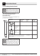
4 External exhaust 4.3.2 Additional parts Part Quantity To p C abinet Template and 1 Rear Wall Template 1 Installation Instructions 1 Separately Packed Grease Filters 2 Exhaust adaptor 1 Glass tray 1 Turntable ring 1 You will find the installation hardware contained in a packet with the unit. Check to make sure you have all these parts. NOTE: Some extra parts are included.
4 External exhaust 4.
Installation 5 5.1 Placement of the mounting plate 5.1.1 Removing the microwave oven from the carton/ removing the mounting plate 5. Remove the screws from the mounting plate. This plate will be used as the rear wall template and for mounting. Reinstall the screws into the holes where they were removed. 5.1.2 Finding the wall studs 1. Find the studs, using one of the following 1. Remove the installation instructions, filters, methods: glass tray and the small hardware bag.
Installation 5 Plate position—beneath framed recessed cabinet bottom NOTE: IT IS VERY READ IMPORTANT AND FOLLOW IN THE TO THE DIRECTIONS INSTALLATION BEFORE PROCEEDINGINSTRUCTION REAR WALL TEMPLATE.WITH THIS S This Rear mounting Wall Template serves plate and outlet. to position to locate the horizontal the bottom 1. Use a level exhaust accurately. to check that the template 2. Locate is positioned and right side mark at least one stud of the centerline.
5 Installation 3/8" TO EDGE 12" NOTE: IT IS VERY IMPORTANT TO READ AND FOLLOW THE DIRECTIONS IN THE INSTALLATION INSTRUCTIONS BEFORE PROCEEDING WITH THIS REAR WALL TEMPLATE. This Rear Wall Template serves to position the bottom mounting plate and to locate the horizontal exhaust outlet. 1. Use a level to check that the template is positioned accurately. 2. Locate and mark at least one stud on the left or right side of the centerline.
5 Installation 5.2 Installation types (choose A, B or C) this microwave oven is designed for adaptation to the following three types of ventilation: •• Outside Top Exhaust (Vertical Duct Type A) Adaptor in Place for Outside Top Exhaust This microwave is shipped assembled for Recirculating. Select the type of ventilation required for your installation and proceed to that section. C 5.2.1 Outside top exhaust (vertical duct type A) installation overview A1. Attach Mounting Plate to Wall A2.
5 Installation A1. Attach Mounting Plate to Wall Attach the plate to the wall using toggle bolts. At least one wood screw must be used to attach the plate to a wall stud. 1. Remove the toggle wings from the bolts. 2. Insert the bolts into the mounting plate through the holes designated to go into drywall and reattach the toggle wings to 3⁄4” (19 mm) onto each bolt. A Be careful to avoid pinching fingers between the back of the mounting plate and the wall. 4. Tighten all bolts.
5 Installation A3. Adapting microwave blower for 4. Place the blower unit back into the opening. outside top exhaust AFTER: Fan Blade 1. Place the microwave in its upright position, with Openings Facing Top the top of the unit facing up. Remove the screw that holds the blower plate to the microwave. Remove and save the screw holding the blower motor to the microwave. Blower Plate Back of Microwave Back of Microwave Blower Motor Screw 2. Carefully pull out the blower unit.
5 Installation A4. Check for proper damper operation Blower Plate Exhaust Adaptor A If filler blocks are not used, case damage may occur from overtightening screws. 1. Lift microwave, tilt it forward, and hook slots at back bottom edge onto four lower tabs of mounting plate. 2. Rotate front of oven up against cabinet bottom. Back of When mounting the microwave Microwave oven, thread power cord through hole in bottom of top cabinet.
5 Installation 4. Attach the microwave oven to the top cabinet. Cabinet Front Cabinet Bottom Shelf 7. Tighten the outer two screws to the top of the microwave oven. (While tightening screws, hold the microwave oven in place against the wall and the top cabinet.) Filler Block Equivalent to Depth of Cabinet Recess Self-Aligning Screw Microwave Oven Top 5. Insert 2 self-aligning screws through outer top 8. Install grease filters. See the Owner’s Manual cabinet holes. Turn two full turns on each screw.
5 Installation A7. Connecting ductwork 1. Extend the house duct down to connect to the exhaust adaptor. 2. Seal exhaust duct joints using furnance duct tape for high temperature applications.
5 Installation 5.2.2 Outside back exhaust (horizontal duct type B) 3/8" TO EDGE along the dotted line. Trim the rear wall template 12" TO NOTE: IT IS VERY IMPORTANT THE DIRECTIONS READ AND FOLLOW INSTRUCTIONS IN THE INSTALLATION WITH THIS BEFORE PROCEEDING REAR WALL TEMPLATE. serves to position the bottom This Rear Wall Template the horizontal exhaust mounting plate and to locate outlet. the template is positioned 1. Use a level to check that accurately. one stud on the left or 2.
5 Installation B2. Remove blower plate Remove and save the screw that holds the blower plate to the microwave. Lift off the blower plate. Blower Plate Back of Microwave B3. Attach the mounting plate to the wall 3. Place the mounting plate against the wall and insert the toggle wings into the holes in the wall to mount the plate.
5 Installation B5. Adapting microwave blower for 4. Rotate blower unit counterclockwise 180°. outside back exhaust Before Rotation After Rotation 1. Remove and save screw that holds blower motor to microwave. Blower Motor Back of Microwave Back of Microwave Back of Microwave Blower Motor Screw 5. Gently remove the wires from the grooves. Reroute the wires through grooves on other side of the blower unit. 2. Carefully pull out the blower unit.
5 Installation 8. Place the blower unit back into the opening. AFTER: Fan Blade Openings Facing Back End A End B 11. Attach the exhaust adaptor to the rear of the oven by sliding it into the guides at the top center of the back of the oven. Push in securely until it is in the lower locking tabs. Take care to assure that the damper hinge is installed so that it is at the top and that the damper swings freely. Adaptor A Do not pull or stretch the blower unit wiring.
5 Installation A If filler blocks are not used, case damage may occur from overtightening screws. 1. Lift microwave, tilt it forward, and hook slots at back bottom edge onto four lower tabs of mounting plate. C When mounting the microwave oven, thread power cord through hole in bottom of top cabinet. Keep it tight throughout Steps 1–3. Do not pinch cord or lift oven by pulling cord. 1 4. Attach the microwave oven to the top cabinet.
5 Installation 7. Tighten the outer two screws to the top of the microwave oven. (While tightening screws, hold the microwave oven in place against the wall and the top cabinet.) 8. Install grease filters. See the Owner’s Manual packed with the microwave. 5.2.3 Recirculating (non-vented ductless type C) 3/8" TO EDGE along the dotted line.
5 Installation A Make sure the motor wiring has been properly routed and secured, and that the wires are not pinched. C1. Attach the mounting plate to the wall C Before tightening toggle bolts and wood screw, make sure the tabs on the mounting plate touch the bottom of the cabinet when pushed flush against the wall and that the plate is properly centered under the cabinet. A Be careful to avoid pinching fingers between the back of the mounting plate and the wall. 4. Tighten all bolts.
5 Installation C3. Check blower plate Blower Plate 1. Lift microwave, tilt it forward, and hook slots at back bottom edge onto four lower tabs of mounting plate. C When mounting the microwave oven, thread power cord through hole in bottom of top cabinet. Keep it tight throughout Steps 1–3. Do not pinch cord or lift oven by pulling cord. 1 •• Place the microwave in its upright position, with the top of the unit facing up. •• Check to see that the blower plate is correctly installed on the unit. C4.
5 Installation 5. Insert 2 self-aligning screws through outer top 1. Remove screws on top of grille using a #1 cabinet holes. Turn two full turns on each screw. Phillips screwdriver. 2. Open the door. 5 3. Remove the grille. Pull the grille straight off. Charcoal Filter 6 6. Tighten center screw completely. 7. Tighten the outer two screws to the top of the microwave oven. (While tightening screws, hold the microwave oven in place against the wall and the top cabinet.) 4.
6 How to use the product C Before you use your over the range product; 1. Make sure the product has been installed according to instructions. 2. Remove all packing material from the product. 3. Install turntable ring and glass tray in cavity 4. Replace house fuse or turn breaker back on. 5. Plug power cord into a dedicated 15 amp to 20 amp electrical outlet. 6. Read the user manual. 7. Keep installation instructions for the local inspectors’s use.
Avant d'utiliser l'appareil, veuillez lire ce manuel ! Chère cliente, cher client, Merci d’avoir choisi les produits Blomberg. Nous espérons que ce produit, fabriqué dans des installations modernes et soumis à un processus de contrôle qualité rigoureux, vous offre les meilleures performances possibles. C’est pourquoi nous vous recommandons, avant d’utiliser ce produit, de lire attentivement ce manuel et tous les autres documents fournis et de les conserver soigneusement pour toute consultation future.
TABLE DES MATIÈRES 1 Consignes importantes 35 1.1 Consignes générales de sécurité.....................35 1.1.1 Sécurité électrique.............................................36 5.2.3 Recyclage d’air (évacuation sans conduit de type C).........................................................59 6 Utilisation du produit 63 2 Votre four à micro-ondes à convection à hotte intégrée 37 2.1 Vue d'ensemble.......................................................37 2.2 Données techniques........................
1 Consignes importantes 1.1 Consignes générales Avant d’entreprendre l’installation, l’installateur doit vérifier la contide sécurité nuité à la boîte à prises pour s’assuLisez et conservez ces rer qu’elle est adéquatement mise à instructions la terre.
1 Consignes importantes Pour faciliter l’installation et pour votre sécurité, il est recommandé que l’installation de ce produit soit effectuée par deux personnes. Pour votre sécurité, mettez convenablement cet appareil à la terre pour éviter un choc grave ou mortel. Pour diminuer les risques de choc électrique, le cordon d’alimentation de cet appareil est muni d’une fiche à trois broches (mise à la terre) qui correspond à une prise murale à trois broches (prise dotée d’une mise à la terre).
2 Votre four à micro-ondes à convection à hotte intégrée 2.1 Vue d'ensemble A B C 2.2 Données techniques Dimensions du produit Dimensions de découpe A-Hauteur 16.4 ˝ (41.7 cm) Hauteur (Min.) 16.75 ˝ (42.5 cm) B-Largeur 29.9 ˝ (75.9 cm) Hauteur (Max.) 17.0 ˝ (43.2 cm) C-Profondeur 15.0 ˝ (38.2 cm) Largeur (Min.) 30.0 ˝ (76.2 cm) Profondeur (Min.) 12.0 ˝ (30.5 cm) Profondeur (Max.) 14.0 ˝ (35.
3 Dégagements pour l’installation Le rebord inférieur de l'armoire doit être à au moins 30 pouces (76,2 cm) de la surface de cuisson. [12“ (30.5 cm) min.] 163⁄ 4 “ (42.5 cm) 30“ (76.2 cm) 30“ (76.2 cm) min. 2“ (5.1 cm) Dosseret Au moins 66 pouces (167,6 cm) entre le sol et le dessus du four à micro-ondes.
4 Conduite d'évacuation externe 4.1 Installation de la hotte de ventilation C Lisez ces instructions si vous décidez d’évacuer l’air du ventilateur à l’extérieur. Si vous décidez de recycler l’air dans la pièce, rendez-vous au chapitre 5. 4.1.1 Évacuation à l’extérieur par le dessus (exemple uniquement) Le tableau suivant décrit une façon possible d’installer les conduits.
4 Conduite d'évacuation externe 4.1.2 Évacuation à l’extérieur par l’arrière (exemple uniquement) Le tableau suivant décrit une façon possible d’installer les conduits. Longueur équivalente x Nombre = Longueur équivalente Évent mural 40 pi (12,2 m) x (1) = 40 pi (12,2 m) 3 pi Conduit droit (rectangulaire de 3¼ po x 10 po/8.
4 Conduite d'évacuation externe 4.1.3 Raccordement de l’évacuation au conduit L’évacuation pour hotte a été conçue pour être raccordée à un conduit rectangulaire standard de 31⁄4 po x 10 (8,2 x 25,4 cm). Si un conduit rond est nécessaire, utilisez un adaptateur de transition rectangulaire à rond. N’utilisez pas de conduit ayant un diamètre inférieur à 6 po (15,2 cm). 4.1.5 Coudes, adaptateurs de transition, évents de toit et muraux, etc.
4 Conduite d'évacuation externe Coude de 45 degrés 5 pi (1,5 m) x () = Pieds ou m Évent de toiture 24 pi (7,3 m) x () = Pieds ou m Conduit droit rond de 6 po (15,2 cm) ou rectangulaire de 1 pi (0,3 m) x () = Pieds ou m Longueur totale des conduits = Pieds ou m 31⁄4 po x 10 po (8,2 x 25,4 cm) C Si vous utilisez un adaptateur de transition rectangulaire à rond, les coins inférieurs du registre devront être coupés aux dimensions de l’adaptateur au moyen des cisailles de ferblantier afin
4 Conduite d'évacuation externe 4.3.2 Pièces supplémentaires Pièce Quantité Gabarit pour armoire supérieure et 1 Gabarit pour mur arrière 1 Instructions d’installation 1 Filtres à graisse emballés séparément 2 Adaptateur de conduit d’évacuation 1 Plateau en verre 1 Anneau de plateau tournant 1 Vous trouverez les pièces de quincaillerie dans un sachet fourni avec l’appareil. Vérifiez que vous avez reçu toutes ces pièces. Vérifiez que vous disposez de toutes ces pièces.
4 Conduite d'évacuation externe 4.4 Outils et matériaux nécessaires To urn evis P hil l ip s no 1 Cisailles de ferblantier (pour couper le registre, si nécessaire) Crayon Ciseaux (pour couper le gabarit, si nécessaire) Ruler or tape measure and straight edge Perceuse électrique avec forets de 3/16 , 1⁄2 et 5⁄8.
5 Installation 5.1 Mise en place de la plaque de montage 5.1.1 Enlèvement du four à microondes de la boîte/enlèvement de la plaque de montage 5. Enlevez les vis de la plaque de montage. Cette plaque sera utilisée comme gabarit pour le mur arrière et pour le montage. Remettez en place les vis retirées préalablement. 5.1.2 Localisation des montants 1. Localisez les montants en utilisant une des 1.
5 Installation 5.1.3 Établissement de l’emplacement de la plaque murale sous votre armoire Emplacement de la plaque—sous une armoire dont le fond est doté d’un surplomb avant Emplacement de la plaque—sous une armoire à fond plat Tracez une ligne sur le mur arrière correspondant à la profondeur du surplomb avant. NOTE: IT IS VERY READ IMPORTANT AND FOLLOW IN THE TO INSTALLATIOTHE DIRECTIONS BEFORE N INSTRUCTION PROCEEDING REAR WALL TEMPLATE.
5 Installation 3/8" TO EDGE 12" NOTE: IT IS VERY IMPORTANT TO READ AND FOLLOW THE DIRECTIONS IN THE INSTALLATION INSTRUCTIONS BEFORE PROCEEDING WITH THIS REAR WALL TEMPLATE. This Rear Wall Template serves to position the bottom mounting plate and to locate the horizontal exhaust outlet. 1. Use a level to check that the template is positioned accurately. 2. Locate and mark at least one stud on the left or right side of the centerline.
5 Installation 5.2 Types d’installation (choisissez A, B ou C) Ce four à micro-ondes est équipé à l’usine en vue d’un Recyclage. Choisissez le type d’évacuation approprié à votre installation et rendez-vous à cette section. C Ce four à micro-ondes est conçu pour s’adapter aux trois types d’évacuation suivants : •• Évacuation à l’extérieur par le dessus (Type A conduit vertical) 5.2.
5 Installation A1 . Fixation de la plaque de montage au mur A Veillez à ne pas pincer vos doigts entre l’arrière de la plaque de montage et le mur. Fixez la plaque au mur à l’aide des boulons à ailettes. Utilisez au moins une vis à bois pour fixer la 4. Serrez tous les boulons. Éloignez la plaque du plaque à un montant. mur pour faciliter le serrage des boulons. 1. Retirez les ailettes des boulons. A2 . Utilisez le gabarit supérieur pour la prépa2.
5 Installation A3 . Adaptation du ventilateur du four à miAvant la rotation Après la rotation cro-ondes pour l’évacuation à l’extérieur par le dessus 1. Placez le four à micro-ondes en position verticale avec le dessus de l’appareil orienté vers le haut. Retirez la vis qui maintient la Arrière du four Arrière du four plaque du ventilateur à l’appareil. Retirez la vis à micro-ondes à micro-ondes qui maintient la plaque du ventilateur au moteur du ventilateur et conservez-la. 4.
5 Installation 7. Fixez l’adaptateur d’évacuation au-dessus de la plaque du ventilateur en le coulissant dans les guides de la plaque du ventilateur. Poussez-le convenablement jusqu’à ce qu’il s’insère dans les fentes de blocage. Assurez-vous que la charnière du registre est installée et que le registre bouge librement. Adaptateur Guide Arrière du four à micro-ondes Languette de verrouillage A4 .
5 Installation 5 1 2 6 3. Insérez une vis à auto-alignement dans le trou situé au centre de l’armoire supérieure. 6. Serrez complètement la vis centrale. Fixez temporairement le four en effectuant 7. Serrez les deux vis extérieures qui se trouvent deux rotations complètes de la vis après sur la partie supérieure du four à micro-ondes. l’engagement des filetages. (Vous le serrerez (Lorsque vous serrez les vis, maintenez le complètement plus tard.
5 Installation A6. Ajustement de l’adaptateur d’évacuation Ouvrez l’armoire supérieure et ajustez l’adaptateur d’évacuation pour le raccorder au conduit d’évacuation du domicile. Plaque du ventilateur Registre Arrière du four à micro-ondes Faites glisser l'adaptateur d'évacuation au besoin pour l'ajustement de l'avant à l'arrière et l'ajustement latéral. A7. Connexion au conduit 1. Tirez sur le conduit du domicile pour le raccorder à l’adaptateur d’évacuation. 2.
5 Installation 5.2.2 Évacuation à l’extérieur par l’arrière (conduit horizontal de type B) 3/8" TO EDGE along the dotted line. Trim the rear wall template 12" TO NOTE: IT IS VERY IMPORTANT THE DIRECTIONS READ AND FOLLOW INSTRUCTIONS IN THE INSTALLATION WITH THIS BEFORE PROCEEDING REAR WALL TEMPLATE. serves to position the bottom This Rear Wall Template the horizontal exhaust mounting plate and to locate outlet. the template is positioned 1. Use a level to check that accurately.
5 Installation B2. Retrait de la plaque du ventilateur Retirez la vis qui maintient la plaque du ventilateur à l’appareil et conservez-les. Soulevez la plaque du ventilateur. Plaque du ventilateur Arrière du four à micro-ondes 3. Placez la plaque de montage contre le mur et insérez les boulons à ailettes dans les trous du mur pour la fixer.
5 Installation B5. Adaptation du ventilateur du 4. Retournez l’ensemble du ventilateur dans le sens antihoraire sur 180°. four à micro-ondes pour l’évacuation à l’extérieur par l’arrière Avant la rotation Après la rotation 1. Retirez la vis qui maintient le moteur du ventilateur à l’appareil et conservez-les. Moteur du ventilateur Arrière du four à micro-ondes Vis du moteur du ventilateur 2. Tirez sur le ventilateur avec précaution.
5 Installation 8. Replacez l’ensemble du ventilateur dans 11. Fixez l’adaptateur d’évacuation à l’arrière du l’ouverture. four en le coulissant dans les guides situés au centre, à la partie supérieure arrière du four. APRÈS : Ouvertures des pales du Poussez-le convenablement jusqu’à ce qu’il ventilateur orientées vers l'arrière s’insère dans les fentes de blocage. AssurezExtrémité A vous que la charnière du registre est installée sur le dessus et que le registre bouge librement.
5 Installation A Si vous n’utilisez pas d’entretoises, le boîtier peut subir des dommages si les vis sont trop serrées. 1. Soulevez le four à micro-ondes, inclinez-le vers l’avant et glissez les fentes qui se trouvent sur le rebord arrière inférieur sur les quatre languettes inférieures de la plaque de montage. C Lors du montage du four à microondes, faites passer le cordon d’alimentation dans le trou situé au fond de l’armoire supérieure. Gardez-le bien tendu durant les étapes 1 à 3.
5 Installation 7. Serrez les deux vis extérieures qui se trouvent sur la partie supérieure du four à micro-ondes. (Lorsque vous serrez les vis, maintenez le four à micro-ondes contre le mur et l’armoire supérieure.) 8. Installez les filtres à graisse. Reportez-vous au manuel d’utilisation qui accompagne le four à micro-ondes. 5.2.3 Recyclage d’air (évacuation sans conduit de type C) 3/8" TO EDGE along the dotted line.
5 Installation Assurez-vous que le câblage du moteur a été effectué et correctement fixé, et que les câbles ne sont pas coincés. C1. Fixation de la plaque de montage au mur A C Avant de resserrer les boulons à ailettes et la vis à bois, assurez-vous que les languettes de la plaque de montage touchent le fond de l’armoire lorsque vous poussez la plaque contre le mur et que la plaque est bien centrée sous l’armoire. A Veillez à ne pas pincer vos doigts entre l’arrière de la plaque de montage et le mur.
5 Installation C3. Vérifiez la plaque du ventilateur Plaque du ventilateur A Si vous n’utilisez pas d’entretoises, le boîtier peut subir des dommages si les vis sont trop serrées. C Lors du montage du four à microondes, faites passer le cordon d’alimentation dans le trou situé au fond de l’armoire supérieure. Gardez-le bien tendu durant les étapes 1 à 3. Ne coincez pas le cordon et ne vous en servez pas pour soulever le four. 1.
5 Installation Avant de l'armoire Étagère inférieure de l'armoire Entretoise Équivalent à la profondeur du rebord de l'armoire Vis à auto-alignement Partie supérieure du four à micro-ondes 8. Installez les filtres à graisse. Reportez-vous au 5. Insérez 2 vis à auto-alignement dans les trous manuel d’utilisation qui accompagne le four à situés à l’extérieur de l’armoire supérieure. micro-ondes. Effectuez deux rotations complètes de chaque C5. Installez ou changez le filtre à vis.
6 Utilisation du produit Insérez le treillis vers le haut C Avant d’utiliser votre micro-ondes à hotte intégrée ; 1. Assurez-vous que le produit a été installé conformément aux instructions. 2. Retirez tous les matériaux d’emballage de l’appareil. 3. Installez l’anneau de la plaque tournante et le plateau en verre dans la cavité 4. Replacez les fusibles de la maison ou remettez le disjoncteur en marche. 5. Branchez le cordon d’alimentation à une prise électrique dédiée de 15 à 20 ampères. 6.
www.blomberginternational.com info@blomberginternational.