
Installation Manual


17 / 63 EN
Over The Range Convection Microwave Oven / Installation Manual
5
Installation
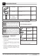
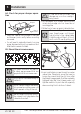
5.2 Installation types (choose
A, B or C)
this microwave oven is designed for adaptation to
the following three types of ventilation:
• Outside Top Exhaust (Vertical Duct Type A)
Adaptor in Place for
Outside Top Exhaust
• Outside Back Exhaust (Horizontal Duct Type B)
Adaptor Must Be
Moved to the Back for
Outside Back Exhaust
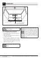
• Recirculating (Non-Vented Ductless Type C)
C
This microwave is shipped assem-
bled for Recirculating. Select the
type of ventilation required for your
installation and proceed to that sec-
tion.
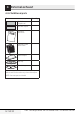
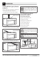
5.2.1 Outside top exhaust
(vertical duct type A)
installation overview
A1. Attach Mounting Plate to Wall
A2. Prepare Top Cabinet
A3. Adapting Microwave Blower for
A4. Check Damper Operation
A5. Mount Microwave Oven
A6. Adjust Exhaust Adaptor
A7. Connect Ductwork
A
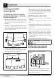
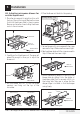
Make sure the screws for the blower
motor and blower plate are securely
tightened when they are reinstalled.
This will help to prevent excessive
vibration.
A
Make sure the motor wiring has
been properly routed and secured,
and that the wires are not pinched.
3/8"
TO
EDGE
NO
TE
: IT IS
VERY
I
MPOR
TANT TO
READ AND FO
LLOW
T
HE
DIRECTIO
N
S
IN THE INSTALLA
T
ION INSTRU
CTI
O
NS
BE
FO
RE PR
O
CEEDING
WITH
T
H
IS
REAR W
A
LL TEM
PLATE.
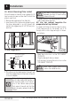
Th
i
s
Re
a
rWall Te
mplate ser
v
e
s to positio
n th
e
botto
m
mountin
g
p
l
atea
nd
to loc
a
te the ho
r
i
zon
ta
l e
x
h
au
s
t
ou
t
let.
1. Us
e a l
e
v
elto
ch
ec
k
th
at the
t
emplate
is
p
o
s
itioned
accu
r
a
tely
.
2. L
o
cate
a
ndm
a
r
k
at lea
s
t o
nestud on th
e
le
ft or
right
side of th
e c
e
nte
rl
i
ne.
It is imp
orta
nt to use a
t le
ast
one
wo
od
s
c
re
w
mo
unted
fi
r
mly
i
n
a
s
tud
to supp
ort the w
e
ight
of
th
e mic
r
owa
v
e.
M
a
r
k
t
w
o a
d
di
ti
onal, ev
e
n
lys
pa
ced
lo
c
atio
n
s f
o
r the
s
upplied tog
gle bol
t
s.
3. Dr
i
ll
h
ole
s in th
e mar
ked lo
c
atio
ns.
Wher
e t
h
er
e is
a
s
tu
d, d
r
il
l
a 3/1
6"
hole for
woo
d scr
e
w
s
.
F
o
r h
oles
th
at
do
n
o
t lin
e upw
ith
a
stud, d
r
il
l 5
/8
"
h
ole
s
fo
r
to
gg
le bo
lts.
DO
NOT
I
N
STALL
T
HE
MOU
NTI
N
G
P
L
ATE
AT T
HIS
T
IME.
4. Rem
o
v
e th
e te
mplate fr
o
m
the r
ea
r
wal
l.
5.Rev
iew
th
e In
stall
a
tionInstruc
tio
n book
for y
ou
r
ins
tal
la
ti
on si
tuat
i
on
.
Locat
e and m
ark
holes
to ali
gn with holes
in t
he
mounting
pl
ate.
IMP
ORTANT
:
LO
CA
TE
AT LEA
ST ONE
STUD
O
N EI
T
HERSI
D
E O
F
TH
E CENT
E
R
LI
N
E.
MARK
THE LO
CATIO
NF
O
R 2 ADDIT
IO
N
AL, EVENLY
SP
ACE
D T
OGGLE
BOLTS IN
THE MO
UN
TING
PLATE
AREA
.
Locate and mar
k
holes to align with holes in t
he
mounting
plate.
IMP
ORTANT
:
LO
C
A
TE AT LEAST O
N
ESTUD ON EITHER SI
D
E OF
TH
E
CENTE
R
LI
N
E
.
MARK
T
HE LO
CATIO
NFO
R 2 ADDITIONA
L, EV
ENL
Y
SPACED
TOG
GLE BO
LTS IN
THE MO
UN
TING PLATE
AREA
.
Trim the r
e
ar
wall tem
plat
e along
the do
tt
ed
line.
Trim the rear wal
l t
em
pla
t
e along
the dotted line.
12"
4"
Da
rl
e
vuelt
a
a
la
ho
ja
pa
rac
o
ns
ul
t
a
r
la
v
e
r
s
i
ón
en
Es
pa
ño
l.