
Installation Manual

Four à micro-ondes à convection à hotte intégrée / Manuel d’installation
54 / 63 FR
5
Installation
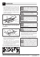
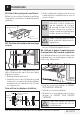
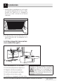
5.2.2 Évacuation à l’extérieur par
l’arrière (conduit horizontal de
type B)
3/8
"
TO
EDG
E
NO
TE
: IT IS
VERY I
MPORTANT TO
READ AND FO
LLO
WT
HE
D
IRECTIO
N
S
IN THE INSTALLATION INSTRU
CTI
O
NS
BEF
O
RE PR
OCEEDING
WITH
T
HIS
REAR WALL TEM
PLA
T
E
.
Th
i
s R
ea
r
Wa
ll T
e
mpla
te
s
e
r
ve
s
to po
sitio
n th
e
b
o
tto
m
mou
nting pl
a
te
a
nd
to lo
cate th
e h
o
ri
zon
tal exh
aust
ou
t
le
t.
1
. Us
e a l
e
vel
to
ch
e
c
k th
at the t
empla
te
is pos
ition
ed
a
ccur
ate
l
y
.
2. L
o
c
ate
a
nd
mark
a
t le
a
s
t o
ne
stu
d
on thele
ft o
r
righ
t s
id
e
of the
ce
n
te
rl
i
n
e
.
It is im
po
rtant to u
se
a
t le
ast
one
wo
od
scre
w
mo
unte
d
fir
mly
i
n a
s
tud to support the weigh
t
of
the mic
r
ow
ave. Mar
k
tw
o a
d
di
tion
a
l, e
venlyspa
c
ed
lo
c
ation
s f
or the
suppl
ied
toggle
bo
l
t
s.
3. Dri
ll
h
ol
es in
th
e
marked lo
catio
ns.
Whe
re t
h
e
re is
a stud,
d
r
ill
a 3/16" h
ole for
woo
d s
cr
e
w
s.
F
o
r h
oles
that
d
o not lin
e up
w
ith a
s
tu
d, d
r
il
l 5
/8
"
h
o
le
s fo
r
to
ggl
e bo
lts
.
DO
NO
T
IN
S
T
A
L
L T
HE
MO
U
NT
I
N
G
P
L
A
T
E
A
T T
HIS
T
IME.
4. Re
m
ove the te
mplate
fr
om
the r
ear wal
l.
5.R
e
vie
h
tw e In
stallationIns
t
r
uction bo
ok for y
ou
r
installa
tio
n
s
i
tuat
ion.
Locat
e and m
ar
k
holes
to ali
gn wi
th holes
i
n t
he
mounting
p
l
ate.
IMPO
RTANT
:
LO
C
A
T
E AT LEA
ST
O
N
E
STUD O
N EITHER
SID
E O
F
TH
E CENTERLIN
E
.
MARKTHE LO
CATION
FOR 2 ADDITION
AL, EVENLY
SP
ACE
D T
O
G
GLE
BO
LTS
IN THE MO
UN
TING
PLATE
AREA
.
Locate and mar
k
hol
es
to al
i
gn with holes
in the
.et
al
p
g
n
i
t
nu
o
m
IMPO
RTANT
:
LO
CAT
E AT LEAST ON
E
STUD O
N EI
THER SI
DE O
F
TH
E
CENT
ER
LINE.
MARK
T
HE LO
CATIO
N
F
O
R 2 ADDITION
A
L, EV
ENLY
SP
ACED
TO
G
GLE
BO
LTS IN
THE MO
UN
TING
PLATE
AREA
.
Trim the r
ear wall temp
late along
t
he dotted
line.
Trim t
he
rear
wal
l t
em
pla
t
e along
t
h
e dotted line.
12"
4"
Da
r
l
ev
u
e
ltaa
laho
j
apa
r
a
consu
l
ta
r
la
vers
i
ó
ne
nEs
paño
l
.
Vue d’ensemble de l’installation
B1. Préparation du mur arrière
B2. Retrait de la plaque du ventilateur
B3. Fixation de la plaque de montage au mur
B4. Préparation de l’armoire supérieure
B5. Ajustement du ventilateur
B6. Installation du four à micro-ondes
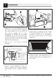
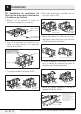
A
Assurez-vous que les vis du moteur
du ventilateur et de la plaque du
ventilateur sont correctement ser-
rées lorsque vous les remettez en
place. Cela permet d’éviter des vibra-
tions excessives.
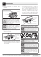
A
Assurez-vous que le câblage du mo-
teur a été effectué et correctement
fixé, et que les câbles ne sont pas
coincés.
B1. Préparation du mur arrière pour
l’évacuation à l’extérieur par l’arrière
Vous devez percer une ouverture dans le mur ar-
rière pour l’évacuation à l’extérieur.
3
/
8" TO E
DGE
NOTE
: IT IS VE
RY IMPOR
T
ANT
TO
READ
A
ND FOLL
OW
TH
E
DIR
ECTIONS
IN THE IN
STA
L
SNI
N
OI
TAL
TR
U
CTIO
NS
BEFO
RE PR
OCEED
ING
WITH
THI
S
REAR
W
ALL
TEMP
LATE
.
T
his
Re
ar
Wall
Tem
pl
a
te
s
erv
esto p
osit
i
on
t
hebottom
m
ounting
pla
tea
nd
t
o
loc
ate
t
hehor
iz
o
nt
alexhaust
out
let
.
1. Us
e
alevel t
o
checkt
hat
the
tem
pla
t
e
isposi
tioned
accurat
ely.
2.
Loc
at
e
andmark a
t
l
ea
stone stud on t
he
lef
tor
right
side of
th
e
c
e
nter
line.
I
tis im
portant
t
o
use
at
leas
t
on
ewood
screw
m
oun
t
e
df
irmly
ina stud
tos
upport
t
he
wei
ght
of
them
i
crowave.M
ar
k
twoa
dditional,
e
v
enlyspaced
loca
t
i
on
sfor
t
hesupplied
t
og
glebolt
s.
3.
Drill
h
olesin t
h
e
m
ark
ed
l
oca
tions.Where t
h
ereis
a st
ud,
drill
a3/
1
6"
ho
lefor
woodscrews.
F
o
r
holes
that
donot line
up
wit
ha stud,
d
r
il
l5
/8
"
holes
f
or
toggle
b
olts.
DO
NO
TINS
T
ALL
T
HE
M
OUNTI
NG
P
LATE
ATTHI
S
T
IM
E.
4.
Remo
v
e
t
hetem
plat
e
f
rom
t
he
rearwall.
5.
R
eviewth
e
I
nst
allation
I
n
s
truc
t
ionboo
kf
or
y
our
installationsit
uat
io
n.
Lo
cate
and
mar
k hol
es to
a
lig
n with ho
les
in the
mou
nting plate.
IMP
O
RTA
NT:
LOCATE AT LEA
ST ON
E
STU
D
ON
EITHER SIDE
O
F
THE
C
ENTERLINE.
M
A
R
K TH
E LOC
AT
ION FOR
2 ADDITI
O
NAL
,
EVEN
LY
SPACE
D TOGG
LE BOLTS IN THE MOU
NTIN
G
PLA
TE
AREA.
Lo
cate
and
mar
k hol
es to
alig
n w
ith holes
in the
mountingplate.
IMPORTA
NT:
LO
CATE
AT LEAST ON
E STU
D O
N EIT
H
ER SIDE
O
F
THE CE
N
TER
LINE.
MARK TH
E
L
OCAT
ION FOR
2 AD
DIT
I
O
NAL
, EVEN
LY
SP
AC
E
D
TOGG
LE BOLTS
IN THE
MOU
NTI
NG PLATE
AREA.
Trim
therea
r wall te
mplate a
l
o
n
g the dotted
line
.
Tri
m
the
r
ea
r
wall
template a
l
ong
the
d
otted
line
.
1
2
"
4"
Dar
levuelta
ala
hojapar
acon
sul
tarla
ve
r
sión
en
E
spañ
ol.
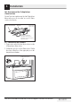
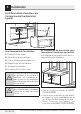
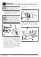
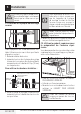
• Lisez les instructions relatives au GABARIT
POUR MUR ARRIÈRE.
• Collez-le au mur arrière avec du ruban adhésif,
en l’alignant sur les trous préalablement percés
pour les trous A et B de la plaque de montage.
• Percez l’ouverture conformément aux
instructions sur le GABARIT POUR MUR ARRIÈRE.