Over The Range Microwave Oven Installation Manual BOTR30102SS EN FR | TINSKB302MRR0_BOTR30102SS_Blomberg OTR_Install Manual.
CONTENTS 1 MOUNTING SPACE..............................3 2 WALL CONSTRUCTION......................4 3 ELECTRICAL GROUNDING INSTRUCTIONS...................................5 4 HOOD EXHAUST DUCT......................6 Exhaust connection.................................................6 Rear exhaust...........................................................6 Maximum duct length..............................................6 5 TOOLS RECOMMENDED FOR INSTALLATION....................................
1 MOUNTING SPACE Please read all instructions thoroughly before installing the Over The Range Microwave Oven. Two people are recommended to install this product. If a new electrical outlet is required this must be completed by a qualified electrician before the Over-the-range microwave oven is installed. See ELECTRICAL GROUNDING INSTRUCTIONS. Min. 12" (304.8 mm) Max. 13" (330.2 mm) 16 5/16" This oven requires a mounting space on a wall as shown in Figure 1.
2 WALL CONSTRUCTION This Over-the-range microwave oven should be mounted against and supported by a flat vertical wall. The wall must be flat for proper installation. If the wall is not flat, use spacers to fill in the gaps. Wall construction should be a minimum of 2 in x 4 in (51 mm x 102 mm) wood studding and 3⁄8 in (10 mm) or more thick dry wall or plaster/lath.
3 ELECTRICAL GROUNDING INSTRUCTIONS This appliance must be grounded. This oven is equipped with a cord having a grounding wire with a grounding plug. It must be plugged into a wall receptacle that is properly installed and grounded in accordance with the National Electrical Code and local codes and ordinances. In the event of an electrical short circuit, grounding reduces risk of electric shock by providing an escape wire for the electric current.
4 HOOD EXHAUST DUCT When the hood is vented to the outside, a hood exhaust duct is required. All ductwork must be metal; do not use plastic duct. Check that all connections are secure. Please read the following carefully: Exhaust connection The hood exhaust has been designed to connect to a standard 3 1⁄4 in x 10 in (82.5 mm x 254 mm) rectangular duct. If round duct is required, a rectangular-to-round adapter must be used.
5 TOOLS RECOMMENDED FOR INSTALLATION • • • • • • • • • • Phillips screwdriver Electric drill 1 1⁄2 in (38 mm) wood bit or metal hole cutter (if metal cabinet is used) 1⁄2 in (12.7 mm), 5⁄8 in (15.8 mm) and 3⁄32 in (2.3 mm) drill bits Scissors Pencil Tape Measure tape Saw to cut exhaust opening (if needed) Protective drop cloth for product and range—you may also use carton for protection Over The Range Microwave Oven / Installation Manual TINSKB302MRR0_BOTR30102SS_Blomberg OTR_Install Manual.
6 INSTALLATION HARDWARE The following is a list of parts you may need for installing your Over-the-range microwave oven. You will find the installation hardware contained in a packet with the unit. Check to make sure you have all these parts. Item 1 Part Quantity 1 Lag screws - 1⁄4" x 1 13⁄16" (6.3 mm x 45.7 mm) 2 2 Toggle bolts and nuts - 3⁄16" x 2 11⁄16" (4.7 mm x 68.6 mm) 2 3 Cabinet mounting bolts - 1⁄4" x 3 1⁄8" (6.
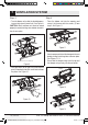
7 VENTILATION SYSTEM This Over-the-range microwave oven is designed for adaptation to three types of hood ventilation systems. Select the type required for your installation. Step 2 • Remove the screws (3) for blower attachment and save screws. See Figure 7. A. Recirculating: Non-vented, ductless operation The unit is shipped assembled for recirculating. NOTE: 1. The exhaust damper assembly is not required for recirculating operation. 2.
7 VENTILATION SYSTEM Step 3 Step 4 • Turn the blower unit so that the fan blade openings are facing back (rear of unit). See Figure 9. CAUTION: Wires to blower unit must be routed properly to avoid pinching wires before reinstallation of cover plate. • Place the blower unit into the opening and secure it to the oven with the screws (3) from step 2. See Figure 11.
7 VENTILATION SYSTEM C. Vertical ventilation system Step 1 & 2 A-1 Ventilation motor. See Section B, steps 1 and 2 for access to the blower motor. Also see Figure 8. of the microwave and attach the damper to blower motor cover by sliding it into the guides at the blower motor cover. See Figures 16, 17. • Ensure that the damper hinge is on the front and the damper swings free into the wall outlet. Step 3 • Turn the blower unit so that the fan blade openings are facing upward. See Figure 14.
8 OVEN INSTALLATION of the wall between the mounting plate and the end of the toggle nut, (in closed position). If you do not leave this space, the toggle nut will not open on the other side of the wall. This oven cannot be properly installed without referring to the mounting instructions found on both templates. Read and follow mounting information on both top cabinet template and wall template. Mounting plate Step 1- Setup position Mounting plate • Draw a line down the middle of the studs.
9 MOUNTING OVEN TO THE WALL IMPORTANT: Do not grip or use handle during installation. Preparation of top cabinet You need to drill holes for the top support screws and a hole large enough for the power cord to fit through. • Read the instructions on the top cabinet template • Tape it underneath the top cabinet • Drill the holes, following the instructions on the template. NOTE: the top cabinet template must be taped to the underside of the top cabinet before proceeding with installation.
10 CONNECTING DUCTWORK • Extend the house duct down to connect to the exhaust adapter. Seal exhaust duct joints using duct tape. See Figure 25. • Install the grease filters. Refer to the User Manual for installation steps. • Plug in the power cord. House Duct Figure 25 14 / 29 EN Over The Range Microwave Oven / Installation Manual TINSKB302MRR0_BOTR30102SS_Blomberg OTR_Install Manual.
11 CHECK LIST FOR OPERATION 1. Make sure the unit has been installed according to all of the installation instructions, the top cabinet template and wall template. 2. Remove all packing material from the oven. 3. Plug in the power cord. 4. Read the User Manual. 5. Keep this Installation Manual for the local electrical inspector’s use. Over The Range Microwave Oven / Installation Manual TINSKB302MRR0_BOTR30102SS_Blomberg OTR_Install Manual.
TABLE DES MATIÈRES 1 ESPACE DE MONTAGE.....................17 2 CONSTRUCTION DU MUR................18 3 INSTRUCTIONS POUR LA MISE À LA TERRE.............................19 4 CONDUIT DE SORTIE DE LA HOTTE....................................20 Raccordement du conduit de sortie......................20 Échappement à l’arrière........................................20 Longueur maximale des tuyaux............................20 5 OUTILS RECOMMANDÉS POUR L’INSTALLATION....................
1 ESPACE DE MONTAGE Veuillez lire attentivement toutes les instructions avant d’installer le four à micro-ondes à hotte intégrée. Deux personnes sont recommandées pour installer ce produit. Si une nouvelle prise électrique est requise, celleci doit être effectuée par un électricien qualifié avant d’installer le four à micro-ondes à hotte intégrée. Voir INSTRUCTIONS DE MISE À LA TERRE ÉLECTRIQU. Min. 304,8 mm (12 po) Max.
2 CONSTRUCTION DU MUR Ce four à micro-ondes à hotte intégrée doit être monté contre et soutenu par une paroi verticale plate. Le mur doit être plat pour une installation adéquate. Si le mur n’est pas plat, utilisez des entretoises pour remplir les écarts. La construction du mur doit être d’au moins 51 mm x 102 mm (2 po x 4 po) et des clous en bois de 10 mm / 3⁄8 po ou plus épais ou de plâtre / latte.
3 INSTRUCTIONS POUR LA MISE À LA TERRE Cet appareil doit être mis à la terre. Ce four est équipé d’un cordon avec fil de mise à la terre et une fiche pour mise à la terre. Il doit être branché dans une prise murale installée correctement et mise à la terre conformément au Code national de l’électricité ainsi qu’aux codes et règlements locaux. Dans l’éventualité d’un court-circuit, la mise à la terre réduit le risque d’électrocution en fournissant un fil de sortie pour le courant électrique.
4 CONDUIT DE SORTIE DE LA HOTTE Si la hotte est ventilée vers l’extérieur, un conduit de sortie est nécessaire. Tous les conduits doivent être en métal; n’utilisez absolument jamais de tuyauterie en plastique. Vérifiez que tous les raccords sont fixés solidement. Veuillez lire attentivement ce qui suit : Raccordement du conduit de sortie L’échappement de la hotte a été conçu pour être raccordé à un tuyau rectangulaire standard de 82.5 mm x 254 mm (3 1⁄4 po x 10 po).
5 OUTILS RECOMMANDÉS POUR L’INSTALLATION • • • • • • • • • • Tournevis Phillips Perceuse électrique Ciseaux Crayon Ruban à mesurer Ruban adhésif Foret pour bois ou foret emporte-pièce pour le métal (si armoire en métal) de 38 mm (1 1⁄2 po) Forets de 12,7 mm (1⁄2 po), 15,8 mm (5⁄8 po) et 2,3 mm (3⁄32 po) Scie pour découper l’orifice d’échappement (si nécessaire) Linge ou tissu de protection pour l’appareil et la cuisinière; vous pouvez aussi utiliser un carton Four à micro-ondes à hotte intégrée / Manuel d
6 QUINCAILLERIE D’INSTALLATION La liste qui suit comprend les pièces dont vous pourriez avoir besoin pour installer votre four à micro-ondes à hotte intégrée. La quincaillerie d’installation est fournie dans un sac accompagnant l’appareil. Assurez-vous d’avoir toutes ces pièces en votre possession. Profitez-en pour vous familiariser avec chacune des pièces.
7 SYSTÈME DE VENTILATION Ce four à micro-ondes à hotte intégrée est conçu pour s’adapter à trois types de systèmes de ventilation à hotte. Sélectionnez le type requis pour votre installation. Étape 2 • Retirez les vis (3) de fixation du ventilateur et conservez les vis. Voir la figure 7. A. Recirculation fonctionnement non ventilé et sans tuyau L’appareil est expédié prêt à être utilisé en mode de recirculation. REMARQUE : 1.
7 SYSTÈME DE VENTILATION Étape 3 Étape 4 • Tournez le ventilateur afin que les ouvertures du ventilateur soient tournées vers l’arrière (de l’appareil). Voir la figure 9. MISE EN GARDE : Les fils du ventilateur doivent être acheminés correctement avant la réinstallation de la plaque pour éviter les pincements. • Placez le ventilateur dans l’ouverture et fixez-le au four avec les vis (3) de l’étape 2. Voir la figure 11.
7 SYSTÈME DE VENTILATION C. Système de ventilation vertical Étape 1 & 2 A-1 Moteur de ventilation. Voir la section B, étapes 1 et 2 pour accéder au moteur du ventilateur. Voir également la figure 8. Step 3 de l’orifice d’évacuation du four à micro-ondes et fixez l’amortisseur au capot du moteur du ventilateur en le faisant glisser dans les guides situés sur le capot du moteur du ventilateur. Voir les figures 16 et 17.
8 INSTALLATION DU FOUR Assurez-vous de laisser un espace d’au moins l’épaisseur du mur entre la plaque de montage et la fin de l’écrou à ailettes (en position fermée). Si vous ne laissez pas cet espace, l’écrou à ailettes ne pourra pas s’ouvrir de l’autre côté du mur. Ce four ne peut pas être installé correctement sans consulter les instructions de montage imprimées sur les deux gabarits. Lisez et suivez les informations de montage imprimées sur les gabarits pour l’armoire supérieure et le mur.
9 FIXATION DU FOUR À MICRO-ONDES AU MUR IMPORTANT : Ne tenez ou n’utilisez pas la poignée pendant l’installation. Préparation de l’armoire supérieure Vous devez percer des trous pour les vis de montage supérieures et un trou suffisamment grand pour y passer le cordon d’alimentation. • Lisez les instructions sur le plateau pour placard supérieur. • Fixez le gabarit sous l’armoire à l’aide de ruban adhésif. • Percez les trous conformément aux instructions sur le gabarit.
10 CONNEXION DES CONDUITS • Abaissez le conduit de la maison pour le raccorder à l’adaptateur d’échappement. Scellez les joints du tuyau de sortie avec du ruban à conduits. Voir la figure 25. • Installez les filtres à graisse. Reportez-vous au guide d’installation pour les étapes d’installation. • Branchez le cordon d’alimentation. Conduit de la maison Figure 25 28 / 29 FR Four à micro-ondes à hotte intégrée / Manuel d’installation TINSKB302MRR0_BOTR30102SS_Blomberg OTR_Install Manual.
11 LISTE DE VÉRIFICATION POUR LE FONCTIONNEMENT 1. Vérifier que l’appareil a été installé conformément à toutes les instructions d’installation et celles du plateau pour placard supérieur et du plateau du mur. 2. Le cas échéant, retirer du four le matériel d’emballage restant. 3. Brancher le cordon d’alimentation. 4. Lire le manuel d’utilisation. 5. Garder toutes les guide d’installation à l’intention de l’inspecteur en électricité.
TINSKB302MRR0_BOTR30102SS_Blomberg OTR_Install Manual.
TINSKB302MRR0_BOTR30102SS_Blomberg OTR_Install Manual.
www.blomberginternational.com info@blomberginternational.com Document number : TINSKB302MRR0 TINSKB302MRR0_BOTR30102SS_Blomberg OTR_Install Manual.