Built-in Hob installation Manual O O IMPORTANT Installer should leave these instructions with appliance, Consumer should read these instructions before using the appliance and should retain them for future reference. 24” Models 30” Models 38" Models 125.9108. 3UR AMT .08.
READ ALL INSTRUCTIONS BEFORE INSTALLATION rift WARNING: Read all safety Instructions before using the product. If the information in this manual is not followed exactly, a fire or explosion may result causing property damage, personal injury or death. — Do not store or use gasoline or other flammable vapors and liquids in the vicinity of this or any other appliance. ~— WHAT TO DO IF YOU SMELL GAS Do not try to light any appliance. Do not touch any electrical switch. Do not use any phone in your building.
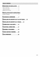
AEE OF CONTENT, [I PREPARING FOR INSTALLATION 4 Tools you will need Tools you may nee Materials you may needlewomen.
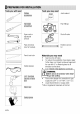
PREPARING. ed © 1 FOR INST, Phillips Servility Pen-end or adjustable wrench Pipe wrenches {one for backup) Pencil and ruler Safety glasses TRUED Bellini Eli casaba Safety jives i Tools you may need = © Joint sealant Pipe fittings Shut off valve Flexibility connector Materials you may need e Gas line shut-off valve » To reduce the possibility of gas leaks, apply Teflon tape or a thread compound approved for use with LP or Natural gases fo all threaded connections.
Insignia BEFORE YOU BEGIN . Before beginning the installation, switch power off at service panel and look the service disconnecting means to prevent power from being switched on accidentally.
war of potential exposure to such sub chances. IMPORTANT: His product contain a chemical known to he State of California 10 cause cancer, birth, , or other reproductive harm. = This appliance can cause low-level exposure to same of the substances listed, including benzene. formaldehyde, carbon monoxide, and toluene. + Call service for obtaining replacement parts. Contact information can be found at the last page of the user manual.
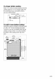
Provide adequate clears between the Installation of a listed microwave oven or cook top and adjacent combustible surfaces. cooking appliance over the cookie shall These dimensions must be met for safe use of conform 10 the installation Instructions packed your cook top. with that appliance. Allow 30° (76.2 om) minimum clearance Built-in oven installation, shall conform to the between boomers and bottom of unprotected installation instruction packed with the built-in wood or metal cabinet. oven.
if a drawer bottom cook top Allow 7/16" minimum vertical clearance from the cook top bottom or minimum depth from the counter top) to any combustible surfaces, such as a cabinet drawer, .
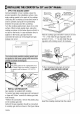
THIN STALLING THE COOK TOP for 1. APPLY THE SEALING GASKET During installation of your cookie, place the product parallel to the installation surface. Also. apply sealing gasket to the parts of the cookie contacting the countering as described below in order to prevent any liquid from penetrating between the product and the counter top. Turn the cook top Upside down; place it on a flat surface.
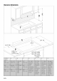
opening. Be sure the Trent edge of the counter top is parallel to the cook top, Make final check that all required clearances are met. 4. LOCATE RETAINER BRACKETS Ramada the retainer brackets from the literature ¢ Cook lop ~~ Counter top package. : Retainer brackets NOTE: The retainer brackets MUST be installed © Sosa { ERST OE RETAINER BRAKES meet local codes or, in their absence, with the 5.
THIN STALLING THE COOK TOP for 1. APPLY THE PUTTY During installation of your cookie, place the product parallel to the installation surface. Also. apply sealing gasket to the parts of the cookie contacting the countering as described below in order to prevent any liquid from penetrating between the product and the counter top. Turn the cook top Upside down; place it on a flat surface.
Wrench (19 mm347 opening. Be sure the front edge of the counter top is parallel to the cookie. Make final check that all required clearances are met, 4. INSTALL THE RETAINER BRACKETS Install the retainer brackets to the bottom of the cook top unit. Then snug the bolts against the bottom of the counter top as shown. Sore 1 2 3 Installation clamp 4 Counter NOTE: The retainer brackets MUST be installed to meet local codes or, in their absence, with the National Electrical Core ANSHAN No, 70, latest edition.
CONNECTION 10 The gas connection is located at rear right bob tom of the cook top. Shut off main gas supply valve before disconnecting he old cook top and keep it off until the new hook-up has been completed. If not already present, install gas shut off valve in an easily accessible location, Make sure all users know where and bow to shut off the gas supply 10 the range. NOTICE: bi installer must inform the consumer of the location of the gas shut-off valve.
24” GAS | CONNECTION {A a NET ante ire A. Male pips thread wit B. Sorting gasket 2 |B. Regulator provided Adapter ) R IC Outlet 3 NET ©. Regulator provided wile unit { female pipe thread « Oubliette" NPT famine pipe tale 172° NPT fatal thread . AL | pipe tread . fl 12 NPT mammal pipe A | o Ade Adapter | DF comer E F. Flexible connector 1 Fl wo Hoff vak G. Adapter {To Mania troll vale H. Maniacal shut-off valve @.
Flexible Connector Method (24” Models) 1. Install a manual gas fine shut-off valve (Hin the gas line in an easily accessed location outside of the cook top. Be sure everyone operating the cookie knows where and how to shut off the gas supply to the cook lop. 2. install male 1/2” flare union adapter £) to the 1/2" NPT internal thread at inlet of pressure regulator (D). Use a backup wrench on the pressure regulator {03 fitting to prevent damage. 3.
[ELECTRICAL CONNECTIONS [ORIENTATE: [Electrical installation should comply with rational and local codes. The appliance, when installed, must be electrically grounded in accordance with focal codes or, in the absence of local codes, with the National Electrical ode, PAN 70 or the Canadian Electric Code, C54 022.102, [IMPORTANT: This scarp must be grounded! ARMING Await fire hazard or electrical shew Dg not ise an adapter pug. Do nut use an extension cord.
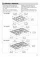
Assemble THE BURNERS 30” 4 burners model =, 307 5 burners model Sees 3. Place the grates on the cookie. For maxi ) 36" 5 burners model mum stability, these grates should only be used in their proper position. Because of the varied burner sizes, the side grates cannot be exchanged nor can any of the grates he rotated front to back. ft is important that the position of the middle grates.
TE CHECKPOINT OF BURNERS 1. Turn on power at breaker Make sure all gas and electrical connection is done safely before checking for ignition of surface boomers. Tum on power at breaker. 2, Verify the cap and grates placement Make sure all burners gre in their comet locations and fully assembled before attempting to separate any burner. 3, ignite the burners Gas boomers are controlled with gas hob knobs.
Flame characteristics The burner flame should be soft blue in color and stable with no yellow tips, excessive noise or fluttering. It should bum completely around the burner cap Below Flames: Further adjustment is required Yellow Tips on Outer Cores: Normal for LP Gas. Soft Blue Flames: Normal for Natural Gas If the flame is completely or mostly yellow, verify that the regulator is set for the correct gas type and correct injectors are used on the burners, After adjustment, retest.
natural gas. When converting to LP gas, the conversion mast be performed by a qualified LP gas installer. 22/EN The conversion instructions and LP orifices are supplied with your cook top. Keep these instructions and the orifices in case you want to convert back to natural gas.