Dishwasher Installation Manual FOR MODELS DWT 14210 NBL00 DWT 14220 NBL00 DWT 14240 NBL00 DWT 15210 NBL00 DWT 15220 NBL00 DWT 15240 NBL00 DWT 15211 NBL00 DWT 35220 NBL00 DWT 35240 NBL00 DWT 35200 NBL00 DWT 36210 NBL00 DWT 36220 NBL00 DWT 36240 NBL00 DWT 36211 NBL00 DWT 15221 NBL00 DWT 15241 NBL00 DWT 34210 NBL00 DWT 34220 NBL00 DWT 34240 NBL00 DWT 34200 NBL00 DWT 35210 NBL00 USA DWT 36221 NBL00 DWT 36241 NBL00 DWT 36200 NBL00 DWT 36201 NBL00 DWT 37210 NBL00 DWT 37220 NBL00 DWT 37240 NBL00 DWT 37200 NBL
Installation Manual For Dishwasher Models DWT 14210 NBL00 DWT 14220 NBL00 DWT 14240 NBL00 DWT 34210 NBL00 DWT 34220 NBL00 DWT 34240 NBL00 DWT 34200 NBL00 DWT 35210 NBL00 DWT 15210 NBL00 DWT 15220 NBL00 DWT 15240 NBL00 DWT 35220 NBL00 DWT 35240 NBL00 DWT 35200 NBL00 DWT 36210 NBL00 DWT 36220 NBL00 DWT 15211 NBL00 DWT 15221 NBL00 DWT 15241 NBL00 DWT 36240 NBL00 DWT 36211 NBL00 DWT 36221 NBL00 DWT 36241 NBL00 DWT 36200 NBL00 DWT 36201 NBL00 DWT 37210 NBL00 DWT 37220 NBL00 DWT 37240 NBL00 DWT 37200 NBL00
To prevent accidents, which could cause serious injury or death, as well as machine damage read these instructions before installation and / or use. Contents 1. IMPORTANT SAFETY INSTRUCTIONS..........................................................................................1 1.1 INSPECT THE DISHWASHER.........................................................................................2 1.2 HOW TO CONTACT US .........................................................................................
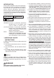
INTRODUCTION Please read this installation manual and particularly the safety instructions completely and carefully. They will save you time and effort and help to ensure optimum dishwasher performance. Be sure to observe all listed warnings and cautions. Look particularly for the icons with exclamation marks inside. The information icon also will provide important references.
Ý Notice : = = = = The dishwasher drain hose must be installed with a drain loop at least 28" (710 mm) off the cabinet floor; otherwise the dishwasher may not drain properly. This dishwasher is intended for residential use only, and should not be used in commercial establishments. New installation - If the dishwasher is a new installation, most of the work must be done before the dishwasher is moved into place.
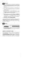
2. TOOLS WHICH MAY BE NEEDED Pipe Wrench Wire Cutter Drill Hole Saw Hammer Wire Stripper (T20) Tape Measure Torx Screwdriver Phillips Screwdriver Adjustable Wrench Scot Screwdriver Scissors Level Brush Pencil 3. MATERIALS WHICH MAY BE NEEDED (Additional materials may be required to comply with local codes) Hot Water Supply Line - Minimum 3/8" O.D. copper tubing or metal braided dishwasher supply line.
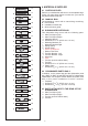
a. x1 b. x1 c. x1 d. x6 e. x1 f. x1 g. x1 h. x1 i. x4 j. x1 k. x1 l. x1 m. x3 n. x4 o. x1 p. x1 r. x2 s. x2 t. x2 u. 7 3/4(196,5mm) x1 v. x8 y. x4 4. MATERIALS SUPPLIED 4.1 PARTS SUPPLIED Parts for your dishwasher will come in several plastic bags. Check your parts bags shown to make sure you have all the parts as listed to the left. 4.
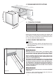
34 - 361/4 (864mm - 920mm) 5. DISHWASHER SPECIFICATIONS 33 7/8- 35 7/8 (861mm - 911mm) 239 (598 /16 mm ) 24m) 0m 1 (6 2 (61 4 0m m) 5.1 TECHNICAL FEATURES Load capacity axax) mm 4 2 m 0m 61 ( 12 place settings Permissible water pressure 4.35 - 145 psi (0.
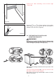
Position the cable extending at the bottom edge (Figure B). Figure B Remove 2 15/16" - 3 15/16" (75mm-100mm) of the cable's outer casing, and then remove 3/8"-1/2" (9-13mm) of insulation from each wire. (Figure C) Figure C 6.2 PREPARATION FOR INSTALLING MOUNTING BRACKETS WARNING Dishwasher must be secured to adjacent cabinetry using the mounting brackets provided. Failure to do this may cause damage to property or bodily injury.
(861mm - 911mm) 6.3. ADJUSTING HEIGHT 33 7/8- 35 7/8 Insert the short leg supports into the legs of the dishwasher. 11/8 (50mm) Supplied (4) 11/8 (50mm) Adjust the front foot level with the adjusting wrench to balance and raise the dishwasher to the enclosure height. Adjust the rear foot level with a screwdriver to balance and raise the dishwasher to the enclosure height.
6.5 PREPARING THE WATER CONNECTION (A) Install an easily accessible shut-off valve (not supplied) in the water supply line. All solder connections must be made before the water line is connected to the dishwashers water inlet valve. Water can also be supplied to the dishwasher by using a flexible braided hose line. Check with your plumbing supply sources for the proper hose and 90° elbow and necessary fittings for the water supply line. This material is not supplied, and must be purchased separately.
6.6 DRAIN PREPARATION The dishwasher drain hose may be connected to the drain plumbing in one of three ways (Figure A, B, C). Ý Notice : Either one of the above methods must be used or the dishwasher will not operate properly. = A hose that attaches to a sink spray can burst if it is installed on the same water line as the dishwasher. If your sink has one, it is recommended that the hose be disconnected and the hole plugged. = The total length of the drain hose is 76 3/4 (1950mm.
7 PLACEMENT OF DISHWASHER INTO THE OPENING Now place the dishwasher into the opening and get ready to connect all hoses and electrical connections. CAUTION Make sure all hoses and electrical wire are pulled through the side opening of the cabinet, no hoses are kinked and all slack is taken out as shown in the above figure. 7.1 DRAIN HOSE CONNECTION, WATER SUPPLY & ELECTRICAL CONNECTIONS 7.1.1 DRAIN HOSE CONNECTION Connect the drain hose to the drain plumbing. 1.
7.1.
Figure E After installing one clip for each side push the dishwasher into the cabinet (Figure E). Figure F Figure F Figure G Figure G 12 Note that while pushing the dishwasher into the cabinet, electrical cable and water supply hose must move in the channels to the front (Figure F). Fix the second clip for both sides (Figure G).
7.1.3 WATER SUPPLY CONNECTION Water supply may be connected to the dishwasher in one of two ways: = With metal braided hose. = With copper tubing. After connections are made turn on the water supply to check for leaks. CAUTION = Hot water supply line: Use minimum 3/8 O.D. copper tubing or metal braided dishwasher supply line. = Temperatures required for soldering and sweating will damage the dishwashers water inlet valve so if any such operation is needed, keep the heat source min.
WARNING = Improper connection of the equipment-grounding conductor can result in a risk of electric shock. Check with a qualified electrician or service representative if you are in doubt whether the appliance is properly grounded. Install a strain relief (not supplied) into the opening on the kick plate.
7.1.6. FASTEN JUNCTION BOX 1. Pull the wires into the junction box. Be sure that the wire nuts do not loosen. 2. Replace the cover on the junction box. 3. Secure the cover with the screws (Figure D). Figure D 7.2 READJUSTING FOOT LEVELS Now that the dishwasher is in the cabinet you must readjust the feet to bring the dishwasher up to the required height and attach it underneath the countertop. 1.
7.3 ADJUSTING THE MOVABLE TOE KICK Now that you have successfully installed the dishwasher, you need to attach the toe kick to the dishwasher. The two piece toe kick can be adjusted to the height and depth needed for your kitchen. Be sure to use the slotted toe kick in the front and the other behind it. They slide into each other. A 1. Insert the movable toe kick brackets into the channel ( A). 2.
If the enclosure height is above 341/14 (870 mm) use o and p labelled toe kicks together. Make sure the slotted toe kick p is on the outside so you can adjust height of the toe kick. Installation should be done following the steps illustrated in the figures A, B and C respectively. A p o 1. Align the toe kick (o) and (p) (A). B 2. Secure toe kicks to brackets with screws (t) after adjusting the height of the slotted toe kick (p) (B). t s 3. Attach caps (s) as shown in the supply bags (C).
3. Lay the schematic over the door from the bottom up and mark holes on the wooden door as shown in the drawing (Figure A). ) m 8 ,2m 1 (22 6 11 / 1 A A A A 6 ) 11 / 1 m 8 ,2m 1 (22 11 / 1 6 8 1,2m 2 (2 m ) 4. Place the plastic mounting brackets over the marked holes and the side tabs must be flush with the edge of the wooden door (Figure B). Side Tab B 5. Attach the two mounting brackets to the wooden door with eight screws (Ø 1/8" x 5/8" (Ø 3.5 mm x 14 mm) (Figure C).
X8 6. Cut the small tabs on the mounting brackets off (Figure A). 7. Cut the side tabs on the plastic mounting brackets off. A 8. Mount the wooden door onto the dishwasher with the plastic mounting brackets which you have attached (Figure B). B 9. Open the door and remove the two caps and two screws inside the door at position 1 and 3 (Figure C).
10. Using the four screws Ø 3/16"x 111/16" (Ø 4 mm x 43 mm) provided, attach the wooden door to the dishwasher at position 1 and 3 (Figure A). Ø 3/16" (4mm) x4 y A 11. Check the position of the wooden door and make sure it is aligned properly (Figure B). B 12. Tighten the screws in position 1 and 3 completely after the final alignment (Figure C).
1 3 . Check whether the bottom of the door hits the toe kick of the kitchen cabinet (A). 13.1 If the door hits the toe kick cut the necessary section out of the toe kick (B). 13.2 Apply silicon or sealant to the cut edge of the kitchen cabinet toe kick or paint so it does not absorb moisture.
Ý Notice : If you have a European kitchen or want to install a wooden toe kick to match your kitchen, please refer to one of the two drawings given below. Follow the same instructions on the brackets as for the removable toe kick. Installation should be done following the steps illustrated in the figures A, B, C, D respectively.
Ý Notice : Ý Notice : The installer is responsible for the dishwasher installation. Incorrect installation is not covered by the warranty. 8. INSTALLER CHECKLIST Your installer must have completed and checked the following: = The dishwasher is square and level. = The dishwasher is fastened securely to the cabinetry. = The dishwasher door opens and closes freely. The dishwasher door must close without hitting any cabinetry or counter top. = The inlet water supply is turned on and checked for leaks.
17 1156 01 00-00 USA