Instructions Booklet built-in cooktops Gebrauchsanweisungen kochmulden, Einbauversion GKS 3134 X MMS 3201 X MGS 3101 X GKS 3204 X MKS 3201 X
Important warnings and tips for use ♦ ♦ ♦ ♦ ♦ ♦ ♦ ♦ ♦ ♦ ♦ ♦ IMPORTANT! This manual constitutes an integral part of the appliance. It must be kept intact and within easy reach during the entire life of the cooktop. Please carefully read this manual and all the instructions contained herein before using the appliance. Keep any spare parts supplied with the appliance. Installation must be carried out by a qualified technician and in compliance with current regulations.
COOKTOP SPECIFICATIONS Warnings: This appliance is designed to be built into a housing unit. ♦ The installation class is type 3 for gas and type Y for electric parts. ♦ Housing units must be designed to withstand temperatures of up to 90°C or over. ♦ For correct installation, refer to the relevant paragraph and reference drawings. ♦ The use of a gas cooking appliance produces heat and humidity in the room in which it is installed.
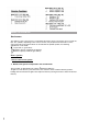
USING THE COOKTOP Gas burners The delivery of gas to the burners is controlled by the knobs shown in fig. 36 that in turn control the taps. The symbols, depending on the various versions, may be printed on the knobs or on the control panel.
Note: If the particular nature of the local gas supply makes it difficult to ignite the burners with the knob turned to the maximum setting, repeat the operation without a pan in position and with the knob turned to the minimum setting. - Burners with safety valves Some models are equipped with safety valves which automatically shut off the gas delivery in the event the burner should, for any reason, go out.
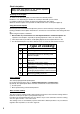
Electric hotplates Never cook food directly on the electric hotplates; always use suitable pots or containers Switching on the hotplate To switch on the electric hotplate, turn the knob to the desired position. Numbers 1 to 6, depending on whether the cooktop is fitted with a power switch or regulator, indicate the settings in progressing temperature (See Table). When the electric hotplate is in operation an indicator led on the control panel lights up.
The intensity of heating for each zone can be adjusted progressively from “0” (off) to “6” 0R “11” (max). When the cooktop is on the indicator light remains lit. When the temperature of the cooking zone is above 70°C, the corresponding “residual heat” indicator lamp lights up to warn that the zone is hot. This lamp remains lit even after the cooking zone is switched off, to signal that the zone is still hot.
INSTALLATION INSTRUCTIONS Important! These instructions are intended for qualified technicians. The appliance must be installed correctly, in compliance with current laws. Before carrying out any operation on the appliance, it must be disconnected from the electricity supply. Fitting the appliance in the worktop The cooktop may be fitted into any worktop, as long as it is heat resistant (minimum temperature of 90°C).
If a hood cannot be installed, an electric extractor fan must be fitted to the outside wall or the window. This electric extractor fan must have a sufficient capacity to guarantee a change of air of the kitchen of at least 3-5 times its volume. Components shown in fig.
Replacing the injectors Remove the grids and burner caps from the cooktop Using a socket wrench, replace the injectors “J” (fig. 43) with the suitable ones for the gas used. Replace the burners. The burners do non require primary air adjustment. Adjustment of minimum setting After replacing the injectors, light the burner and remove the knob. Turn the tap to the minimum setting and insert a screwdriver in the rod: tighten to reduce the flame, loosen to increase the flame. (fig.
MAINTENANCE The appliances do not require any particular maintenance, nonetheless it is advisable to have them checked at least once every two years. If the knobs become difficult to turn, or if there is a smell of gas, shut the gas supply tap and call After-sales service. Faulty taps must be replaced along with their gasket.
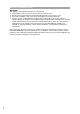
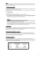
Cat.: II 2H 3+ IT GB ES PT CH IE Tipo di gas/ gas type/ type de gaz/ tipo de gas/ tipo de gás/ gaz type Pressione del gas/ gas pressure/ pression gaz/ presion gas/ pressão gas Bruciatori/ burners/ bruleurs/ quemodores/ bocas de gás/ branders A SR R TC P/F Portata/power inputs/débit gas/capacidad/va zão /debiet Portata/power inputs/débit gas/capacidad/va zão /debiet Max (kW) 1.00 1.75 3.00 3.30 2.90 Min (kW) 0.30 0.44 0.75 1.50 1.
GKS 3134 X GKS 3204 X MMS 3201 X MKS 3201 X MGS 3101 X 12
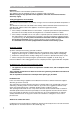
FIG.35 FIG. 37 FIG. 36 0 0 6 1 FIG.34 2 FIG. 38 4 2 10 5 3 1 9 3 4 8 7 6 5 FIG.
FIG. 40 FIG. 41 C:Min. 3 mm D;E; Min.10 mm 14 FIG. 42 FIG. 43 FIG. 44 FIG.
H01A262