642 OWNERS MANUAL for E. B. C.™ Electronic Brew Control ™ AIRPOT AND THERMAL SERVER COFFEE BREWERS MODELS 1080 1082 1082XL 1086 1088 Includes: Installation Use & Care Servicing Instructions Model 1082 Brewer with optional 7752 Airpot E.B.C.™ brewers are protected under U. S. Patent # 5, 704,275 Other U. S. and Canadian patents pending. PRINTED IN UNITED STATES OF AMERICA p/n 75872 Rev.
WARRANTY STATEMENT It also does not apply if the serial nameplate has been removed or unauthorized service personnel perform service. The prices charged by Bloomfield Industries for its products are based upon the limitations in this warranty. Seller’s obligation under this warranty is limited to the repair of defects without charge by a Bloomfield Industries Authorized Service Agency or one of its sub-agencies. This service will be provided on customer’s premises for non-portable models.
TABLE OF CONTENTS WARRANTY STATEMENT SPECIFICATIONS FEATURES & OPERATING CONTROLS PRECAUTIONS & GENERAL INFORMATION AGENCY LISTING INFORMATION INSTALLATION INSTRUCTIONS OPERATION BREWING COFFEE CLEANING INSTRUCTIONS TROUBLESHOOTING SUGGESTIONS SERVICING INSTRUCTIONS Deliming Instructions EXPLODED VIEWS & PARTS LISTS WIRING DIAGRAMS xi 1 2 3 3 4 6 10 11 12 14 20 22 26 Thank You for purchasing this Bloomfield Industries appliance.
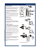
FEATURES AND OPERATING CONTROLS 642 75872 Owners Manual E.B.C. Airpot /Thermal Fig.
PRECAUTIONS AND GENERAL INFORMATION WARNING: ELECTRIC SHOCK HAZARD All servicing requiring access to non-insulated components must be performed by qualified service personnel. Do not open any access panels which require the use of tools. Failure to heed this warning can result in electrical shock. WARNING: INJURY HAZARD All installation procedures must be performed by qualified personnel with full knowledge of all applicable electrical and plumbing codes.
INSTALLATION INSTRUCTIONS READ THIS CAREFULLY BEFORE STARTING THE INSTALLATION IMPORTANT: To enable the installer to make a quality installation and to minimize installation time, the following suggestions and tests should be done before the actual unit installation is started: CAUTION: Equipment Electrical Damage DO NOT plug in or energize this appliance until all Installation Instructions are read and followed. Damage to the Brewer will occur if these instructions are not followed. Unpack the unit.
INSTALLATION INSTRUCTIONS (continued) NSF requires that the brewer be able to be moved for cleaning underneath. A flex line or loops of copper tubing will satisfy this requirement. See Figure 2 below. NOTE: This equipment must be installed to comply with applicable federal, state and local plumbing codes and ordinances. WARNING: ELECTRIC SHOCK HAZARD Fig. 2 Water Supply Installation In some areas, local codes require a backflow preventer (check valve) to be installed on the inlet water line.
OPERATION Fig. 4 Brewer Operation Diagram A. START-UP For initial start-up, or if the brewer has not been used for an extended period of time: ♦ Be sure spray disk and brew gasket are properly installed in the brew head. ♦ Be sure the water supply is properly connected and the water supply valve is turned ON. ♦ Be sure the WATER TANK IS FILLED BEFORE plugging the brewer into a receptacle, or otherwise connecting brewer to electrical power THE WATER TANK MUST BE FILLED.
OPERATION (continued) WATER HEATER Water temperature is sensed by an electronic water temperature probe inserted into the water tank. This temperature signal is fed to the controller. The setpoint temperature is adjustable. The controller sends a command signal to the power board based upon a comparison between the setpoint temperature and actual temperature. See page 15. The power board energizes the heating elements based on the command signal from the controller.
OPERATION (continued) IMPORTANT: DO NOT energize this brewer until the water tank has been filled. Dry firing will damage heating elements. See page 6. ELECTRONIC FEATURES Energizing the Brewer When electric power is applied to the unit, all the lights will flash four times and four beeps will sound. The unit will be OFF. Press the ON/OFF key. Four beeps will sound and all lights will flash once. The POWER indicator will remain ON.
OPERATION (continued) Quality Timer Coffee looses its freshness as it sits on a warmer. The Quality Timer flashes the warmer lights 30 minutes after the last brew to remind you that the coffee is nearing the end of its useful life. Quality Timer is normally set for 30 minutes. It can be set for 20 minutes by moving a jumper on the controller. See page 19. After Hours™ Operation During normal operation, the controller will maintain the precise brewing temperature.
BREWING COFFEE CAUTION: Burn Hazard Exposed surfaces of the brewer, brew chamber and airpot or server may be HOT to the touch, and can cause serious burns. CAUTION: Burn Hazard To avoid splashing or overflowing hot liquids, ALWAYS place an empty airpot or server under the brew chamber before starting the brew cycle. Failure to comply can cause serious burns. CAUTION: Burn Hazard After a brew cycle, brew chamber contents are HOT. Remove the brew chamber and dispose of used grounds with care.
CLEANING INSTRUCTIONS CAUTION: Burn Hazard PROCEDURE: Clean Coffee Brewer PRECAUTIONS: Disconnect brewer from electric power. Allow brewer to cool. FREQUENCY: Daily TOOLS: Mild Detergent, Clean Soft Cloth or Sponge Bristle Brush. Brewing and serving temperatures of coffee are extremely hot. Hot coffee will cause serious skin burns. CAUTION: Electric Shock Hazard Do not submerge or immerse brewer in water. 1. Disconnect brewer from electric power. Allow brewer to cool before cleaning. 2.
TROUBLESHOOTING SUGGESTIONS SYMPTOM POSSIBLE CAUSE SUGGESTED REMEDY Water won’t heat Brewer unplugged or circuit breaker tripped Check power supply cord Check / reset circuit breaker Temperature adjusted too low or set to OFF Turn on and set for desired temperature.
ERROR DETECTION This brewer is designed to perform a continuous internal diagnosis, and to signal faults by flashing all the lights. In fault mode, warmers, heating element and water fill solenoid are turned “off”, and most keypad functions are disabled. Error detection (all lights flashing) will occur under two conditions: • Anytime a temperature in excess of 214ºF is detected. • Temperature does not change by at least 2ºF within 4 minutes of tank heater being energized (HEAT light on).
SERVICING INSTRUCTIONS CAUTION Electric Shock Hazard Opening access panels or removing warmer plates on this brew may expose uninsulated electrical components. Disconnect brewer from electrical power before removing any panel or warmer plate. ACCESS PANELS TOP PANEL: Remove top panel to access hot water tank, thermo probe, heating elements, brew circuit tubing, faucet valve and piping. Top panel is held by two screws at the rear and a retaining lip at the front.
SERVICING INSTRUCTIONS (continued) TEMPERATURE ADJUSTMENT Unplug power cord or turn circuit breaker OFF. Remove top panel. Remove button plug from front panel. CAUTION Electric Shock Hazard These procedures involve exposed electrical circuits. These procedures are to be performed by qualified technical personnel only. Fig. 13 Checking and Adjusting Brew Temperature Pull vent tube out of tank lid and insert a thermometer of known accuracy in vent hole. Reconnect brewer to electrical power.
SERVICING INSTRUCTIONS (continued) IMPORTANT: Water pressure must be between 20 p.s.i and 90 p.s.i. flowing pressure. If water pressure exceeds this value, or if water pressure varies greatly, a pressure regulator must be installed in the water supply line. BREW TIME ADJUSTMENT The amount of water dispensed automatically during a brew cycle is controlled by the SOLENOID TIME dial of the controller. Place empty decanter under brew chamber. Press BREW button.
SERVICING INSTRUCTIONS (continued) REPLACE SOLENOID Unplug power cord. Turn OFF and disconnect water supply from brewer inlet fitting. Remove front panel. Remove two screws holding access door in place. Remove access door and solenoid. Unscrew inlet fitting cap to release solenoid from door. Remove wiring from solenoid. Large end of wrench 86660 can be used to hold solenoid inlet fitting while disconnecting supply line. Fig. 15 Fill Solenoid REPLACE FAUCET SUPPLY HOSE Unplug power cord.
SERVICING INSTRUCTIONS (continued) IMPORTANT: When replacing water faucet coil, also replace seal gaskets. REPLACE HOT WATER FAUCET COIL (Symptom: Brewer drips continuously from brew head, except when faucet valve is turned OFF.) Remove tank lid assembly per above. Remove two hex nuts hot water coil to cover. Pull coil from mounting holes. Reassemble in reverse order.
SERVICING INSTRUCTIONS (continued) SET CONTROLLER JUMPERS Placing the jumper across Q1 sets Quality Time at 20 Minutes. Placing the jumper across Q2 sets Quality Time at 30 Minutes. Removing jumpers from both Q1 or Q2 disables Quality Timer. Placing the jumper across V1 sets Valve Time Range to 60 - 180 seconds. Removing jumper from V1 sets Valve Time Range to 10 - 80 seconds. Fig. 18 Controller Jumpers REPLACE KEYPAD Unplug power cord or turn circuit breaker OFF. Shut off water supply valve.
SERVICING INSTRUCTIONS (continued) CAUTION CHEMICAL BURN HAZARD Deliming chemicals are caustic. Wear appropriate protective gloves and goggles during this procedure. Never siphon deliming chemicals or solutions by mouth. This operation should only be performed by qualified and experienced service personnel. IMPORTANT: DO NOT spill, splash or pour water or deliming solution into or over any internal component other than the inside of the water tank.
SERVICING INSTRUCTIONS (continued) 7. Set the tank back into the brewer. Reassemble the tank lid to the water tank. Make sure the gasket is properly in place, then reinstall the hold-down strap. 8. Reinstall wiring to heating element and thermostat. Reinstall the hi-limit thermostat (if removed). For automatic brewers, reassemble piping for the faucet. Verify that all internal components are dry, then reinstall the top panel. 10.
EXPLODED VIEW & PARTS LIST HOT HOT WATER WATER TANK TANK ASSEMBLY ASSEMBLY PART NO.
EXPLODED VIEW & PARTS LIST (continued) ELECTRICAL COMPONENTS ITEM PART NO.
EXPLODED VIEW & PARTS LIST (continued) INTERNAL PLUMBING COMPONENTS PART NO.
EXPLODED VIEW & PARTS LIST (continued) CABINET COMPONENTS ITEM 21 22 33 34 34a 70 71 642 75872 Owners Manual E.B.C. Airpot /Thermal 72 73 74 75 101 102 103 104 105 106 108 110 200 210 PART NO. DESCRIPTION 63201 87192 8543-42 82727 8543-45 8706-75 82159 84792 82160 84791 8033-55 8033-56 81732 8543-69 Spacer .171 ID x .
WIRING DIAGRAM E.B.C.™ BREWER KEY PAD 1 P1 MODEL VOLTS WATTS AMPS 1080 120 1800 15 1082 120 1800 15 CONTROL BOARD P2 1 TEMPERATURE PROBE POWER BOARD NEUTRAL IN VALVE B 2 WHITE HEATER B HI LIMIT BLACK VALVE A 5 3 INLET VALVE .5 GPM BLACK LINE IN BLACK 1 4 WHITE 26 CHASSIS GROUND WHITE 14 ga HEATING ELEMENT 642 75872 Owners Manual E.B.C.
642 75872 Owners Manual E.B.C.
Bloomfield Industries proudly supports CFESA Commercial Food Equipment Service Association Bloomfield Industries, Inc. Division of Carrier Commercial Refrigeration In US and Canada Telephone: 775-689-5700 Fax: 888-492-2783 Fax: 800-356-5142 (for orders only) website: www.wellsbloomfield.