652 OWNERS MANUAL for E-Max™ AIRPOT and THERMAL COFFEE BREWERS MODELS 2080 2082 2086 2086EX 2088 2088EX Model 2082 Airpot Brewer with optional 7759 Airpot Includes: Installation Operation Use & Care Servicing Instructions Model 2080 Thermal Brewer with optional 7754 Thermal Server E-Max BREWERS are covered under U. S. Patents #5704275, 5862738, 6095031. Other U.S. Patents and Canadian Patents Pending PRINTED IN UNITED STATES OF AMERICA p/n 73574 Rev.
WARRANTY STATEMENT It also does not apply if the serial nameplate has been removed or unauthorized service personnel perform service. The prices charged by Bloomfield Industries for its products are based upon the limitations in this warranty. Seller’s obligation under this warranty is limited to the repair of defects without charge by a Bloomfield Industries Authorized Service Agency or one of its sub-agencies. This service will be provided on customer’s premises for non-portable models.
TABLE OF CONTENTS WARRANTY STATEMENT SPECIFICATIONS FEATURES & OPERATING CONTROLS PRECAUTIONS & GENERAL INFORMATION INSTALLATION AGENCY LISTING INFORMATION OPERATION CLEANING INSTRUCTIONS SERVICING INSTRUCTIONS PLUMBING ELECTRICAL DELIMING WATER TANK TROUBLESHOOTING SUGGESTIONS EXPLODED VIEWS AND PART LISTS WIRING DIAGRAMS Thank You for purchasing this Bloomfield Industries appliance.
FEATURES AND OPERATING CONTROLS 2
PRECAUTIONS AND GENERAL INFORMATION WARNING: Electric Shock Hazard All servicing requiring access to non-insulated components must be performed by qualified service personnel. Do not open any access panels which require the use of tools. Failure to heed this warning can result in electrical shock. WARNING: Injury Hazard All installation procedures must be performed by qualified personnel with full knowledge of all applicable electrical and plumbing codes.
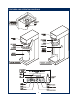
INSTALLATION INSTRUCTIONS READ THIS CAREFULLY BEFORE STARTING THE INSTALLATION IMPORTANT: To enable the installer to make a quality installation and to minimize installation time, the following suggestions and tests should be done before the actual unit installation is started: CAUTION: Equipment Electrical Damage DO NOT plug in or energize this appliance until all Installation Instructions are read and followed. Damage to the Brewer will occur if these instructions are not followed.
INSTALLATION INSTRUCTIONS (continued) For ‘Filter-Ready” units, refer to filter installation and hook-up instructions packed with the brewer. 5. NSF requires that the brewer be able to be moved for cleaning underneath. Loops of copper tubing will satisfy this requirement. NOTE: This equipment must be installed to comply with applicable federal, state and local plumbing codes and ordinances. WARNING ELECTRIC SHOCK HAZARD: 6.
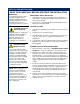
OPERATION OPERATING INSTRUCTIONS IMPORTANT: All E-Max™ brewers are tested and set at the factory. If programming adjustments are necessary, refer to the E-Max™ Programming Manual (p/n/73674). To over-ride the Brew Wait mode, press and hold the BREW key for 3 seconds when the brewer is in Brew Wait mode (i.e. when brew light is flashing). The brew will proceed immediately regardless of water temperature.
OPERATION (continued) USER’S GUIDE 1. Remove the brew chamber from under the spray head. Place one (1) genuine Bloomfield paper filter into the brew chamber. Add your choice of pre-measured ground coffee. Shake the brew chamber gently to level the coffee. Slide the brew chamber back into place. PAPER FILTER BREW CHAMBER WARNING: Burn Hazard. This appliance dispenses very hot liquid. Serious bodily injury from scalding can occur from contact with dispensed liquids. CAUTION: Burn Hazard 2.
OPERATION (continued) PROGRAMMING FEATURES AND OPTIONS 1. View Water Temperature in Tank: To view the water temperature on the screen, the E-Max™ brewer must be ON, and not brewing or in the filling mode. Press and hold the 4th key, and depress the 6th key. The actual water temperature will be displayed for 3 seconds. 2. Daily Brew Count: The E-Max™ maintains a count of the number of completed brews for a 7-day period. To access the count, turn the brewer OFF.
OPERATION (continued) 8. Clock A. Time – Battery Backup. The E-Max™ has a battery backup system which will maintain the proper time during power failures, or when the brewer is unplugged (even for very prolonged periods of time). Normally there will not be a need to set the time except for Daylight Saving Time changes, or moving the brewer to different time zones. B. Changing Day and Time: To change time, turn the E-Max™ off.
OPERATION (continued) 12. View Filter Statistics: To view filter statistics, turn the brewer off. Press and hold the 1st key (Brew), and depress the 3rd (ON/OFF) key. Total water volume will be displayed (TotalVol.). Press the 3rd key to view the Filter Life (FltrLife:). Press the 3rd key to view the percentage of the filter that has been used. (If the filter option is used, the filter life volume needs to be entered in the program – see E-Max™ Programming Manual, Service & Counters Menu.) 13.
CLEANING INSTRUCTIONS PROCEDURE: Clean Coffee Brewer CAUTION: Burn Hazard PRECAUTIONS: Disconnect brewer from electric power. Allow brewer to cool. FREQUENCY: Daily TOOLS: Mild Detergent, Clean Soft Cloth or Sponge Bristle Brush 1. Disconnect brewer from electric power. Allow brewer to cool before cleaning. 2. Remove airpot or thermal server. 3. Remove and empty brew chamber. 4. Remove the spray disk from the brew head: Press up on the spray disk ears, then turn the disk to the left to unlatch.
SERVICING INSTRUCTIONS — PLUMBING FUNCTION 1. Water enters at the inlet fitting of the fill solenoid (32). The solenoid admits water via a command from the controller. NOTE: The solenoid has an internal strainer. To clean the strainer: Shut off water supply. Unscrew the plastic cap protruding from the rear of the brewer. Remove the cap, inlet fitting and washer. With pliers, grasp the bar of the strainer and pull straight out. Wash any debris from the strainer. Note orientation - DO NOT reverse strainer.
SERVICING INSTRUCTIONS — PLUMBING (continued) ITEM DESCRIPTION PART N0. USED ON 1 FAUCET, HOT WATER 8783-1 ALL 2 ASSEMBLY, WATER TANK (120V) ASSEMBLY, WATER TANK (240V) ASSEMBLY, WATER TANK (DUAL VOLTAGE) 83500 83753 84010 2012, 2072 2016, 2074 2015, 2075 6 GASKET, TANK LID 83499 ALL 9 TANK LID 83504 ALL 10 RETAINING CLIP, TANK LID 83506 ALL 11 HOSE, OVERFLOW (2 pc SILICONE 4.5” LONG) 86014 ALL 12 HOSE, FAUCET SUPPLY (SILICONE, 10” LONG) 83538 ALL 13 TUBE, VENT (METAL, 2.
SERVICING INSTRUCTIONS - ELECTRICAL WARNING: RISK OF INJURY The following servicing sections are for operator reference only. All servicing and/or repairs must be performed by a qualified technician FUNCTION 1. Pressing the POWER key energizes the unit. The POWER LED will glow whenever the unit is ON. 2. Automatic fill is accomplished via a FILL SOLENOID (32) and a WATER LEVEL PROBE (7). The probe senses ground through the water in the tank.
SERVICING INSTRUCTIONS - ELECTRICAL (continued) ITEM DESCRIPTION PART N0.
SERVICING INSTRUCTIONS — DE-LIMING HEATER TANK CAUTION - CHEMICAL BURN HAZARD De-liming chemicals are caustic. Wear appropriate protective gloves and goggles during this procedure. CAUTION - CHEMICAL BURN HAZARD Never siphon de-liming chemicals or solutions by mouth. This operation must only be performed by qualified and experienced service personnel. IMPORTANT: DO NOT spill, splash or pour water or de-liming solution into or over any internal component other than the inside of the water tank.
TROUBLESHOOTING SUGGESTIONS If the E-Max™ goes into the error diagnostic mode as outlined below, it will likely be necessary to reset the brewer in order to test individual components. Note the reset procedure below: * For the first four error modes, press and hold CANCEL for 3 seconds, or RE-ENERGIZE the brewer by disconnecting from electric power for 5 seconds, then reconnecting. * From “VALVE FAULT”, the brewer must be RE-ENERGIZED! Using the CANCEL button will not reset the brewer from “Valve Fault”.
EXPLODED VIEW & PARTS LIST AIRPOT BREWER MODELS: 2082, 2083, 2088 18
EXPLODED VIEW & PARTS LIST (continued) ITEM PART # DESCRIPTION QT 1 8763-1 FAUCET HOT WATER 1 2 83500 83753 84010 TANK ASST 8 QT TANK ASSY 8 QT 240V TANK ASSY 8 QT DUAL VOLTAGE 1 3 83480 THERMISTOR 5-1/2" 1 THERMO HI-LIMIT CERAMIC 120V THERMO HI-LIMIT RESET 240V THERMO HI-LIMIT 25A SCREW TERM 1 ITEM PART # DESCRIPTION 42 66385 9012-38 FITTING, CONDUIT 3/4" STR 240V STRAIN RELIEF LIQ.
EXPLODED VIEW & PARTS LIST (continued) THERMAL BREWER MODELS: 2080, 2085, 2086 20
EXPLODED VIEW & PARTS LIST (continued) ITEM PART # DESCRIPTION Q 1 8763-1 FAUCET HOT WATER 1 2 83500 83753 84010 TANK ASST 8 QT TANK ASSY 8 QT 240V TANK ASSY 8 QT DUAL VOLTAGE 1 3 83480 THERMISTOR 5-1/2" 1 4 83949 8552-50 84713 5 THERMO HI-LIMIT CERAMIC 120V THERMO HI-LIMIT RESET 240V THERMO HI-LIMIT 25A SCREW TERM 1 84063 GROMMET .510 x .
WIRING DIAGRAMS 120 VOLT BREWERS AIRPOT and THERMAL MODEL 2080 & 2082 White #9 White #8 Brown #1 Orange/ Black #5 14 ga. Blue #2 Tank Heater 120 Volt 1200 Watts/ 1500 Watts 14 ga. Black #7 Red #3 Brown #1 Blue #2 Black #6 Red #3 14 ga. 14 ga.
WIRING DIAGRAMS (continued) 120/240 VOLT BREWERS AIRPOT and THERMAL MODEL 2086 & 2088 White #8 Tank Heater 3200 Watt 240 Volt White #9 120/240 Single Phase k ac Bl #5 Blue #2 Brown #1 k ac Bl #4 Red #10 Red #3 Brown #1 Blue #2 Black #6 Red #3 Black #13 1 4 2 3 Black #6 Red #11 Black #12 White #7 White #9 White #7 White #8 Green #14 p/n 73852 23 3200
WIRING DIAGRAMS (continued) 240 VOLT BREWERS AIRPOT and THERMAL MODEL 2086EX & 2088EX 24
NOTES 25
Bloomfield Industries proudly supports CFESA Commercial Food Equipment Service Association Bloomfield Industries, Inc. Division of Carrier Commercial Refrigeration In US and Canada Telephone: 775-689-5700 Fax: 888-492-2783 Fax: 800-356-5142 (for orders only) website: www.wellsbloomfield.