712 OWNERS MANUAL for HOT WATER DISPENSER 2 GALLON MODELS: 1222 1222CA 5 GALLON MODELS: 1225 1226 Includes: Installation Operation Use & Care Servicing Instructions Model 1222 Dispenser PRINTED IN UNITED STATES OF AMERICA p/n 76580 Rev.
WARRANTY STATEMENT It also does not apply if the serial nameplate has been removed or unauthorized service personnel perform service. The prices charged by Bloomfield Industries for its products are based upon the limitations in this warranty. Seller’s obligation under this warranty is limited to the repair of defects without charge by a Bloomfield Industries Authorized Service Agency or one of its sub-agencies. This service will be provided on customer’s premises for non-portable models.
TABLE OF CONTENTS WARRANTY STATEMENT SPECIFICATIONS FEATURES & OPERATING CONTROLS PRECAUTIONS & GENERAL INFORMATION AGENCY LISTING INFORMATION INSTALLATION INSTRUCTIONS OPERATION CLEANING INSTRUCTIONS TROUBLESHOOTING SUGGESTIONS SERVICING INSTRUCTIONS Deliming Instructions EXPLODED VIEW & PARTS LIST WIRING DIAGRAMS xi 1 2 3 3 4 6 7 8 9 12 13 16 Thank You for purchasing this Bloomfield Industries appliance.
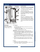
FEATURES AND OPERATING CONTROLS 712 76580 Owners Manual Hot Water Dispenser 2
PRECAUTIONS AND GENERAL INFORMATION WARNING: Electric Shock Hazard All servicing requiring access to non-insulated components must be performed by qualified service personnel. Do not open any access panels which require the use of tools. Failure to heed this warning can result in electrical shock. WARNING: Injury Hazard All installation procedures must be performed by qualified personnel with full knowledge of all applicable electrical and plumbing codes.
INSTALLATION READ THIS CAREFULLY BEFORE STARTING THE INSTALLATION IMPORTANT: To enable the installer to make a quality installation and to minimize installation time, the following suggestions and tests should be done before the actual unit installation is started: CAUTION: Equipment Electrical Damage DO NOT plug in or energize this appliance until all Installation Instructions are read and followed. Damage to the dispenser will occur if these instructions are not followed.
INSTALLATION (continued) NSF requires that the unit be able to be moved for cleaning underneath. A flex line or loops of copper tubing will satisfy this requirement. See Figure 2 below. NOTE: This equipment must be installed to comply with applicable federal, state and local plumbing codes and ordinances. WARNING ELECTRIC SHOCK HAZARD: Fig. 2 Water Supply Installation In some areas, local codes require a backflow preventer (check valve) to be installed on the inlet water line.
OPERATION WATER HEATER Water temperature is sensed by thermobulb inserted into the water tank. Temperature is controlled by a mechanical thermostat. The setpoint temperature is adjustable by turning the thermostat shaft. Excessive temperature will trip the hi-limit safety switch, disabling the heating element. The hi-limit will automatically reset when the dispenser cools. WATER LEVEL Water level is controlled by an electronic controller. The water level probe senses chassis ground through the water.
CLEANING INSTRUCTIONS PROCEDURE: Clean Hot Water Dispenser CAUTION: Burn Hazard PRECAUTIONS: Disconnect dispenser from electric power. Allow dispenser to cool. FREQUENCY: Daily TOOLS: Mild Detergent, Clean Soft Cloth or Sponge Bristle Brush Dispensed water is extremely hot. Hot water will cause serious skin burns. CAUTION: Electric Shock Hazard 1. Disconnect dispenser from electric power. Allow to cool before cleaning. 2.
TROUBLESHOOTING SUGGESTIONS SYMPTOM POSSIBLE CAUSE SUGGESTED REMEDY Water won’t heat Dispenser unplugged or circuit breaker tripped Check power supply cord Check / reset circuit breaker Tank heater switch "OFF" Press switch to "ON" Temperature setpoint too low Adjust thermostat for desired temperature Hi-Limit safety switch tripped Allow to cool hi-limit will selfreset Damaged internal component or wiring Examine wiring & connectors, controller, power board and heating element Repair/replace as
SERVICING INSTRUCTIONS ACCESS PANELS CAUTION REAR PANEL: Electric Shock Hazard Remove rear panel to access hot water tank, thermostat, heating elements, tubing, water level control and plumbing connections. Rear panel is held by four screws at the back. The flanged top portion fits over the body of the dispenser. SOLENOID DOOR: Solenoid door may be removed to aid in solenoid replacement. This access panel is not normally removed. Solenoid door is held by two screws and a retaining lip.
SERVICING INSTRUCTIONS (continued) TEMPERATURE ADJUSTMENT Check temperature at discharge of faucet. Remove thermostat access button plug to access thermostat. Turn thermostat shaft clockwise to increase temperature. IMPORTANT: The thermostat will maintain temperature within ±3ºF. For high altitude locations, thermostat should be adjusted to a maximum temperature equal to the local boiling temperature minus 5º.
SERVICING INSTRUCTIONS (continued) REPLACE HEATING ELEMENT Remove tank lid assembly as detailed on page 10. Remove two hex nuts holding element to cover. Pull element from mounting holes. IMPORTANT: When replacing heating element, also replace seal gaskets. Reassemble in reverse order. REPLACE SOLENOID Unplug power cord. Turn OFF and disconnect water supply from dispenser inlet fitting. Remove rear panel. Remove two screws holding access door in place. Remove access door and solenoid.
SERVICING INSTRUCTIONS (continued) CAUTION CHEMICAL BURN HAZARD Deliming chemicals are caustic. Wear appropriate protective gloves and goggles during this procedure. Never siphon deliming chemicals or solutions by mouth. This operation should only be performed by qualified and experienced service personnel. IMPORTANT: DO NOT spill, splash or pour water or deliming solution into or over any internal component other than the inside of the water tank.
EXPLODED VIEWS AND PARTS LISTS SERVICE KITS 712 76580 Owners Manual Hot Water Dispenser FAUCET REPAIR KITS 84686 Faucet & Shank Complete 8700-25 L Seat Cup (only) SOLENOID REPAIR KITS 83612 Solenoid Complete, Single 120V (1222, 1222CA) 83760 Solenoid Complete, Single 240V (1225, 1226) 85218 Inlet Fitting Kit (includes cap, fitting, washer & screen) 85219 Inlet Strainer (only) 13
EXPLODED VIEW & PARTS LIST 712 76580 Owners Manual Hot Water Dispenser NOTE: Model 1225/1226 shown. Model 1222/1222CA is similar.
EXPLODED VIEW & PARTS LIST (continued) ITEM DESCRIPTION 1222 P/N 1222CA P/N 1225 P/N 1226 P/N 8705-36 8705-36 8705-36 8705-36 8718-31 8718-31 8718-31 8718-31 LIGHT, PILOT AMBER 61178 61178 61178 61178 CONTROL, LOW WATER, 120V 66604 66604 503141 503141 85760 85760 1 WRAP, BODY 2 TANK ASSY 3 PANEL, TOP BACK 4 PLUG, BUTTON 7/8" 5 SUPPORT, TANK 6 LIGHT, PILOT GREEN 7 LABEL, HW DISPENSER 8 9 CONTROL, LOW WATER, 240V 10 SPACER, NYLON 11 PANEL, REAR LOWER 12 SOLENOID, S
WIRING DIAGRAM 2-GALLON MODELS 1222 and 1222CA 712 76580 Owners Manual Hot Water Dispenser 16
WIRING DIAGRAM (continued) 712 76580 Owners Manual Hot Water Dispenser 5-GALLON MODELS 1225 and 1226 17
Bloomfield Industries proudly supports CFESA Commercial Food Equipment Service Association Bloomfield Industries, Inc. Division of Carrier Commercial Refrigeration In US and Canada Telephone: 775-689-5700 Fax: 888-492-2783 Fax: 800-356-5142 (for orders only) website: www.wellsbloomfield.