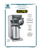
657 BLOOMFIELD INDUSTRIES 2 ERIK CIRCLE, P.O.Box 280 Verdi, NV 89439 U.S.A. Customer Service (775) 345-0444 Ext.502 fax (775) 345-0569 www.wellsbloomfield.com OWNERS MANUAL LX AIRPOT & THERMAL BREWERS MODELS 2280 2282 2286EX 2288EX Includes INSTALLATION OPERATION USE & CARE SERVICE Model 2282 shown with optional airpot p/n 75209 Rev.
WARRANTY STATEMENT All electrical equipment manufactured by BLOOMFIELD INDUSTRIES is warranted against defects in materials and workmanship for a period of one year from the date of original installation or eighteen (18) months from the date of shipment from our factory, whichever comes first, and is for the benefit of the original purchaser, except that: a. airpots carry a 30 day parts warranty only. b. dispensers; i.e., tea and coffee carry a 90 days parts warranty only, excludes decanters.
TABLE OF CONTENTS WARRANTY STATEMENT SPECIFICATIONS FEATURES & OPERATING CONTROLS PRECAUTIONS & GENERAL INFORMATION INSTALLATION INSTRUCTIONS AGENCY APPROVAL INFORMATION OPERATION USERS GUIDE CLEANING INSTRUCTIONS SERVICING INSTRUCTIONS Operational Adjustmets Adjustments Electrical Plumbing De-liming Heater Tank Diagnostics & Troubleshooting EXPLODED VIEW & PARTS LIST In-LineBrewer Airpot ModelsModels Step-Up Models Thermal Brewer Models WIRING DIAGRAMS DIAGRAM Airpot/Thermal Brewer Models Export 240V therm
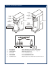
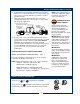
FEATURES & OPERATING CONTROLS CONTROL PANEL HOT WATER FAUCET CONTROL PANEL BREW CHAMBER HOT WATER FAUCET NAMEPLATE BREW CHAMBER NAMEPLATE THERMAL SERVER (BREWING POSITION) AIRPOT (BREWING POSITION) THERMAL BREWER AIRPOT BREWER POSITIONING BRACKET LIFT FOR HOT WATER 1 2 5 1. 2. 3. 5. 6. 7. 8.
PRECAUTIONS AND GENERAL INFORMATION WARNING: Electric Shock Hazard All servicing requiring access to non-insulated components must be performed by qualified service personnel. Do not open any access panels which require the use of tools. Failure to heed this warning can result in electrical shock. WARNING: Injury Hazard All installation procedures must be performed by qualified personnel with full knowledge of all applicable electrical and plumbing codes.
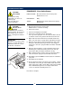
INSTALLATION INSTRUCTIONS READ THIS CAREFULLY BEFORE STARTING THE INSTALLATION IMPORTANT: To enable the installer to make a quality installation and to minimize installation time, the following suggestions and tests should be done before the actual unit installation is started: CAUTION: Equipment Electrical Damage DO NOT plug in or energize this appliance until all Installation Instructions are read and followed. Damage to the Brewer will occur if these instructions are not followed.
INSTALLATION INSTRUCTIONS (continued) 4. A water shut-off valve should be installed on the incoming water line in a convenient location (Use a low restriction type valve, such as a 1/4-turn ball valve, to avoid loss of water flow thru the valve. 5. NSF requires that the brewer be able to be moved for cleaning underneath. A flex line or loops of copper tubing will satisfy this requirement.
OPERATION OPERATING INSTRUCTIONS To over-ride the Brew Wait mode, press and hold the BREW key for 3 seconds when the brewer is in Brew Wait mode (i.e. when brew light is flashing). The brew will proceed immediately regardless of water temperature. This feature should only be used when testing water volume, otherwise the brew will proceed with the water below the precise brew temperature.
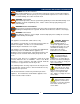
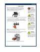
OPERATION USER’S GUIDE 1. Remove the Brew Chamber from under the spray head. Place one (1) genuine Bloomfield paper filter into the Brew Chamber. Add your choice of pre-measured ground coffee. Shake the Brew Chamber gently to level the coffee. Slide the Brew Chamber back into place. PAPER FILTER WARNING: Burn Hazard. This appliance dispenses very hot liquid. Serious bodily injury from scalding can occur from contact with dispensed liquids. CAUTION: Burn Hazard BREW CHAMBER 2.
CLEANING INSTRUCTIONS CAUTION: Burn Hazard Brewing and serving temperatures of coffee are extremely hot. Hot coffee will cause serious skin burns. CAUTION: Electric Shock Hazard Do not submerge or immerse brewer in water. Do not pour or splash water into or over air vents, control panel or warmer plates. IMPORTANT: DO NOT use steel wool, sharp objects, or caustic, abrasive or chlorinated cleansers to clean the brewer or decanters.
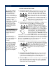
SERVICING — OPERATIONAL ADJUSTMENTS BREW TIMER BREW TEMP (IN SECONDS) 210 100 320 QUALITY TIMER DRIPOUT TIMER AFTER HOURS TIMER (IN 5 MIN INCR) (IN SECONDS) (IN ONE HR INCR) TEMP WATER 70 60 3 PROBE LEVEL PROBE 20 205 OFF 120 30 90 OFF 6 (IN °F) 194 185 OFF UNDER TOP COVER A B C D E CAUTION: Electric Shock Hazard A. B. C. D. E. Adjust Brew Time Adjust Brew Temperature Adjust Quality Timer Adjust Dripout Timer Adjust After Hours Timer 4.
SERVICING INSTRUCTIONS — ELECTRICAL OPERATION SEE PAGE 11 FOR COMPONENT NAMES / NUMBERS 1. Pressing the POWER key energizes the unit. The POWER LED will glow whenever the unit is ON. CONTROLLER WATER LEVEL PROBE FILL SOLENOID FILL BREW TIME DRIP OUT TIME CONTROLLER BREW SOLENOID BREW BREW LINE VOLTAGE HI-LIMIT T STAT BREW CANCEL BREW TEMP CONTROLLER TRIAC HEATING ELEMENT WATER TEMPERATURE WATER TEMP PROBE 2. Automatic fill is accomplished via a FILL SOLENOID (32) and a WATER LEVEL PROBE (7).
SERVICING INSTRUCTIONS — ELECTRICAL 3 7 5 8 4 18 15 20 32 17 120/240V UNITS 4 E-MAX LX ELECTRICAL COMPONENT 3 4 5 7 8 15 17 18 20 32 PROBE, TEMPERATURE (THERMISTOR) THERMOSTAT, HI-LIMIT GROMMET PROBE, WATER LEVEL SLEEVE, WATER LEVEL PROBE ELEMENT, WATER HEATING ASSEMBLY, TRIAC & HEAT SINK BREW SOLENOID CONTROLLER FILL SOLENOID 11 120V UNITS
SERVICING INSTRUCTIONS — PLUMBING OPERATION SEE PAGE 13 FOR COMPONENT NAMES/NUMBERS 1. Water enters at the inlet fitting of the fill solenoid (32). The solenoid admits water via a command from the controller. NOTE: The solenoid has an internal strainer. To clean the strainer: Shut off water supply. Unscrew the plastic cap protruding from the rear of the brewer. Remove the cap, inlet fitting and washer. With pliers, grasp the bar of the strainer and pull straight out. Wash any debris from the strainer.
SERVICING INSTRUCTIONS — PLUMBING ITEM DESCRIPTION PART N0. USED ON ALL 1 FAUCET, HOT WATER 8783-1 2 ASSEMBLY, WATER TANK (120V) ASSEMBLY, WATER TANK (240V) 83500 83753 6 GASKET, TANK LID 83499 9 2280, 2282 2286EX, 2288EX ALL TANK LID 83504 ALL 10 RETAINING CLIP, TANK LID 83506 ALL 11 HOSE, OVERFLOW (2 pc SILICONE 4.5” LONG) 86014 ALL 12 HOSE, FAUCET SUPPLY (SILICONE, 10” LONG) 83538 ALL 13 TUBE, VENT (METAL, 2.
SERVICING INSTRUCTIONS — DE-LIMING HEATER TANK CAUTION - CHEMICAL BURN HAZARD De-liming chemicals are caustic. Wear appropriate protective gloves and goggles during this procedure. Never siphon de-liming chemicals or solutions by mouth. This operation must only be performed by qualified and experienced service personnel. IMPORTANT: DO NOT spill, splash or pour water or de-liming solution into or over any internal component other than the inside of the water tank.
SERVICING INSTRUCTIONS — DIAGNOSTICS & TROUBLESHOOTING) If the E-Max™ LX goes into an error mode as outlined below, it will probably be necessary to reset the brewer in order to test individual components. Note the reset procedure below: * FOR “LOW WATER” OR “OVERHEAT” ERRORS: PRESS & HOLD CANCEL FOR 3 SECONDS, OR RE-ENERGIZE THE BREWER (i.e. unplug for a few seconds, the plug in again.
EXPLODED VIEW — AIRPOT MODELS 16
PARTS LIST — AIRPOT MODELS 17
EXPLODED VIEW — THERMAL SERVER MODELS 18
PARTS LIST — THERMAL SERVER MODELS 19
WIRING DIAGRAM 120 VOLT 20
WIRING DIAGRAM 240 VOLT EXPORT MODELS 21
Bloomfield Industries proudly supports CFESA Commercial Food Equipment Service Association Bloomfield Industries, Inc. Division of Carrier Refrigeration In US PO Box 280, Verdi, NV 89439 Telephone: 775-345-0444 Service: 888-492-2782 Fax: 888-792-2783 website: www.wellsbloomfield.com In Canada Telephone: 877-507-1700 Service: 905-507-1700 Fax: 905-507-1777 website: www.bloomcan.