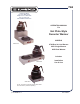
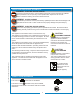
763 10 Sunnen Drive St. Louis, MO 63143 telephone: 314-678-6336 fax: 314-781-2714 www.wellsbloomfield.com OPERATION MANUAL For Hot Plate-Style Decanter Warmer MODELS Model 8702 8708 Dual In-Line Warmer 8851 Single Warmer 8852 Dual Warmer Includes: Model 8852 Installation Use & Care Model 8851 NOTE: All warmers shown with optional 8900-Series Glass Decanters (available separately). p/n 2M-77719 Rev.
WARRANTY STATEMENT All electrical equipment manufactured by WELLS BLOOMFIELD, LLC is warranted against defects in materials and workmanship for a period of one year from the date of original installation or eighteen (18) months from the date of shipment from our factory, whichever comes first, and is for the benefit of the original purchaser, except that: a. airpots carry a 30 day parts warranty only. b. dispensers; i.e., tea and coffee carry a 90 days parts warranty only, excludes decanters.
TABLE OF CONTENTS WARRANTY STATEMENT SPECIFICATIONS FEATURES & OPERATING CONTROLS PRECAUTIONS & GENERAL INFORMATION AGENCY LISTING INFORMATION INSTALLATION INSTRUCTIONS OPERATION CLEANING INSTRUCTIONS Thank You for purchasing this Wells Bloomfield appliance. xi 1 2 3 3 4 5 5 Proper installation, professional operation and consistent maintenance of this appliance will ensure that it gives you the very best performance and a long, economical service life.
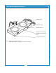
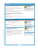
FEATURES AND OPERATING CONTROLS POWER CORD WARMER PLATE WARMER SWITCH OPTIONAL DECANTER (SHOWN FOR POSITION ONLY) IL2044a SLIP-RESISTANT FEET 763 p/n 2M-77719 OpManual Decanter Warmers Fig. 1 Features & Operating Controls Model 8852 shown. Features are similar for all models.
PRECAUTIONS AND GENERAL INFORMATION WARNING: Electric Shock Hazard All servicing requiring access to non-insulated components must be performed by qualified service personnel. Do not open any access panels which require the use of tools. Failure to heed this warning can result in electrical shock. WARNING: Injury Hazard All installation procedures must be performed by qualified personnel with full knowledge of all applicable electrical codes. Failure could result in property damage and personal injury.
INSTALLATION INSTRUCTIONS READ THIS CAREFULLY BEFORE STARTING THE INSTALLATION CAUTION: Equipment Damage DO NOT plug in or energize this appliance until all Installation Instructions are read and followed. Damage to the Brewer will occur if these instructions are not followed. CAUTION: Unstable Equipment Hazard It is very important for safety and for proper operation that the brewer is level and stable when standing in its final operating position.
OPERATION Place a decanter of hot beverage on a warmer plate. Press warmer switch for that warmer plate to ON ( I ). Press warmer switch to OFF (O) when a warmer plate is not in use for any extended period. SUGGESTION: Coffee loses its fresh flavor if allowed to set on a warmer for too long. Discard stale coffee promptly. CAUTION: Burn Hazard Exposed surfaces of the warmer may be HOT to the touch. The warmer plate will be very hot during operation and can cause serious burns on contact.
852 EXPLODED VIEW / PARTS LIST / WIRING DIAGRAM 4 1 2 3 RIGHT WARMER SWITCH 1 2 RE D K AC BL K AC BL W BL RE 7 HI TE TE AC D W ELEMENT HI 6 5 1 2 3 LEFT WARMER SWITCH K W HI TE ELEMENT W HI TE WIRING DIAGRAM 8852 8 9 11 10 POWER CORD GR EE N NOTE: Export Cord White = Blue Black = Brown REPLACEMENT PARTS LIST MODEL 8852 SLIM LINE DOUBLE WARMER 120V, 200 W 220/240V, 200W Export IL2045 8852 Slim Line Double Warmer 8852 Description 1 PLATE COVER WARMER 8852 EU
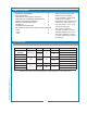
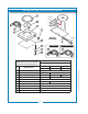
8708 EXPLODED VIEW / PARTS LIST / WIRING DIAGRAM REPLACEMENT PARTS LIST MODEL 8708 STEP-UP DOUBLE WARMER 1 2 UPPER WARMER 6 UPPER WARMER SWITCH ELEMENT b LOWER WARMER SWITCH 7 c ELEMENT a LOWER WARMER 8 4 d 3 POWER CORD 5 9 10 a IL2029 763 p/n 2M-77719 OpManual Decanter Warmers MODEL 8708 STEP-UP DOUBLE WARMER Item No 1 2 3 4 5 6 7 8 9 10 a b c d Part No 2D-70090 E5-71203 A6-71206 E5-71204 E5-70339 A6-WL0412 A6-WL0141 A6-WL0140 2K-70215 2K-70648 2N-70091UL 2N-70635UL 2E-72946 2E-70247 2A
8851 EXPLODED VIEW / PARTS LIST / WIRING DIAGRAM 1 POWER SWITCH 2 3 2 ELEMENT 1 RE D 6 W HI 4 7 5 BL TE AC K WIRING DIAGRAM 8 9 GR EE EU POWER CORD UK 4 11 N 4 10 IL2056 PARTS LIST NOTE: 120V DIAGRAM SHOWN, 220V SAME EXCEPT USE 220V ELEMENT, CORD AND PLUG, WIRE COLORS. DESCRIPTION MODEL 8851S MODEL 8851S MODEL 8851S 120V UK 230V 1 Cover Plate 2 Element Heating 4 Assy.
763 p/n 2M-77719 OpManual Decanter Warmers NOTES
10 Sunnen Drive, St. Louis, MO 63143 telephone: 314-678-6336 fax: 314-781-2714 www.wellsbloomfield.