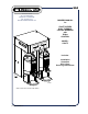
664 10 Sunnen Drive St. Louis, MO 63143 telephone: 314-678-6336 fax: 314-781-2714 www.bloomfieldworldwide.com OWNERS MANUAL for 2790TF-SERIES DUAL THERMAL COFFEE BREWERS with E-Max CONTROL MODEL: 2790TF Includes: Installation Operation Use & Care Servicing Instructions IL2839 Model 2790TF Dual Thermal E-Max Brewer p/n 2M-Z18642 Rev.
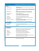
WARRANTY STATEMENT All equipment manufactured by Bloomfield is warranted against defects in materials and workmanship for the time periods listed in the chart starting from the date the equipment is placed into service and is for the benefit of the original purchaser: THE FOREGOING OBLIGATION IS EXPRESSLY GIVEN IN LIEU OF ANY OTHER WARRANTIES, EXPRESSED OR IMPLIED, INCLUDING ANY IMPLIED WARRANTY OF MERCHANTABILITY OR FITNESS FOR A PARTICULAR PURPOSE, WHICH ARE HEREBY EXCLUDED.
TABLE OF CONTENTS Thank You for purchasing this Bloomfield Industries appliance.
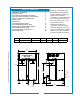
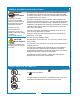
FEATURES AND OPERATING CONTROLS BREWER Model 2790TF BYPASS DIVERTER Control Panel Brew Chamber ON.OFF SWITCH (Rear Panel) BREW CHAMBER ACCESSORIES Hot Water Faucet THERMAL SERVER Water Connection (Bottom Panel) BREW HEAD (BREW CHAMBER REMOVED) BREW NOZZLE SPRAY HEAD GASKET SPRAY DISK CONTROL PANEL LEFT BREWING CONTROLS POWER KEY TANK HEAT INDICATOR DIGITAL READOUT BLOOMFIELD RIGHT BREWING CONTROLS IL2840 Fig 1.
FEATURES AND OPERATING CONTROLS (continued) Brewer Adjustable Legs Allows brewer to be leveled. Also allow clearance for cleaning underneath brewer. Brewing Controls Start or stop brew and select brew volume. Right and left section are independent. Also, used to program brewer in programming mode. Digital Readout Displays information pertaining to brew cycle and status. Displays programming information in programming mode. Hot Water Faucet Hot water dispensed here.
GENERAL INFORMATION AND PRECAUTIONS All servicing requiring access to non-insulated electrical components must be performed by a factory authorized technician. DO NOT open any access panel which requires the use of tools. Failure to follow this warning can result in severe electrical shock. CAUTION: Burn Hazard Surfaces of this brewer can be hot and can cause burns on contact. This appliance is intended for use in commercial establishments only.
INSTALLATION INSTRUCTIONS INSTALL LEGS The brewer is provided with 4” adjustable legs and rubber feet. Be sure the legs are securely screwed into the base of the brewer, and that the rubber feet are properly installed. LEVEL THE UNIT The adjustable legs allow the brewer to be leveled. Set the brewer in its ultimate operating location and check for level with a spirit level Adjust the brewer for level from front-to-rear, and from sideto-side. Be sure all four feet rest firmly on the counter.
INSTALLATION INSTRUCTIONS (continued) Initial set-up must be performed by a qualified installer or qualified service technician. Improper set-up will damage the brewer and void the warranty. DO NOT CONNECT POWER TO BREWER WITH SATELLITES IN PLACE. NOTE: If “NO WATER SENSED” error message is displayed: * Disconnect brewer from electrical power.
OPERATING INSTRUCTIONS 1/2 GALLON 1 GALLON 1-1/2 GALLON 1/2 GALLON 1 GALLON LEFT RIGHT SATELLITE START BREW 1-1/2 GALLON TANK HEAT SATELLITE STOP BREW START BREW STOP BREW POWER IL2526 Fig. 3 Control Panel GETTING STARTED Check the brewer and satellites: Check that the brewer is clean and the drip tray (if used) is empty. Check that the satellites are empty and clean with lids properly installed.
OPERATING INSTRUCTIONS (continued) 1/2 GALLON 1 GALLON 1-1/2 GALLON 1/2 GALLON LEFT 1-1/2 GALLON RIGHT SATELLITE START BREW 1 GALLON TANK HEAT SATELLITE STOP BREW START BREW STOP BREW POWER IL2526 BREWING COFFEE Fig. 4 Operating Controls Prepare the Brew Baskets: Insert one (1) Bloomfield paper filter into each brew chamber. Make sure the filter is properly supported by the wire rack. PAPER FILTER BREW CHAMBER Add a measured amount of grounds to each brew basket.
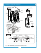
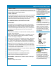
OPERATING INSTRUCTIONS (continued) WATER FLOW WATER LEVEL PROBE VENT (TO BREW HEAD) TEE HOT WATER FAUCET BREW VALVE INLET VALVE HOT WATER TANK BYPASS VALVE BYPASS NOZZLE BREW HEAD BREW CHAMBER W/BYPASS CHANNEL COLD WATER HOT WATER IL2828 664 2M-Z18642 Owners Manual 2790 E-Max Dual Thermal Brewer Fig. 6 Water Flow Diagram INLET The INLET VALVE is controlled by a signal from the CONTROL BOARD. If the WATER LEVEL PROBE does not detect water, the inlet solenoid is opened until water is again sensed.
CLEANING INSTRUCTIONS Brewing and serving temperatures of coffee are extremely hot. Hot coffee will cause serious skin burns. WARNING: Electric Shock Hazard DO NOT immerse or submerge satellites. Fluid may saturate the insulation and short-circuit the receptacle connectors. Electric shock may cause injury and property damage. IMPORTANT: DO NOT use steel wool, sharp objects, or caustic, abrasive or chlorinated cleansers to clean the brewer, brew baskets or satellites.
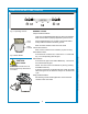
CLEANING INSTRUCTIONS (continued) PROCEDURE: Clean Thermals CAUTION: PRECAUTIONS: Drain Thermal before Cleaning FREQUENCY: Daily TOOLS: Sanitizer, Soft Clean Cloth, Bucket 1. Remove and drain thermals. Remove lids. 2. Remove funnel assembly and clean with mild detergent and warm water. 3. Fill Server 1/4 to 1/2 full with hot water, (use a non-caustic cleaning solution if appropriate). 4. Use a brush to clean the inside of the server. 5. Drain server, rinse & dry the outside surfaces with dry cloth. 6.
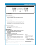
PROGRAMMING INSTRUCTIONS Menu (1st key) Menu Ext (2nd key) Item (3rd key) 1/2 GALLON 1 GALLON (4th key) Decrease (5th key) Increase (6th key) 1-1/2 GALLON 1/2 GALLON 1 GALLON LEFT RIGHT SATELLITE START BREW 1-1/2 GALLON STOP BREW Clock Set (ON Mode) Menu Program (OFF Mode) TANK HEAT SATELLITE POWER START BREW STOP BREW IL2829 Fig. 7 Function Keys NEW MENU SETTINGS Time is held in memory and is battery-backed.
PROGRAMMING INSTRUCTIONS (continued) FEATURES 664 2M-Z18642 Owners Manual 2790 E-Max Dual Thermal Brewer 1. Energizing the Brewer: Turn the brewer on by pressing the POWER key. The brewer will start to fill the tank with the message on the screen “filling…”. With the proper water supply the tank should be filled in about 2½ minutes.
PROGRAMMING (continued) BOILING POINT OF WATER 210 205 IDEAL BREWING TEMPERATURE 200 MAXIMUM TEMPERATURE SETTING 190 ELEVATION (feet above sea level) IL1601 BOILING POINT OF WATER 100 97 IDEAL BREWING TEMPERATURE 94 91 MAXIMUM TEMPERATURE SETTING 0 05 0 1, 20 1, 0 35 0 1, 50 1, 0 65 0 1, 80 1, 0 95 0 0 1, 90 0 75 60 45 0 88 0 15 0 30 0 NOTE: The HEAT LED will glow if the water temperature is too low when the brewer is turned .
PROGRAMMING (continued) 7. Automatic Start-Up in Previous Mode: If the brewer automatic timer is OFF (the factory setting) and power is disconnected, the brewer will start up when power is restored, in the mode it had been in prior to the power disconnection. If the Satellite Brewer has the timer setting ON and power is disconnected, the brewer will start up in the mode that it should be in at the time the power is restored. 8. Brew Volume: The Brewer can have up to 3 different brew volumes on each side.
PROGRAMMING (continued) The factory programming has the After Hours™ mode turned OFF. While in the After Hours mode, the POWER LED will flash continuously. 12. After Hours™: The After Hours™ can be programmed to come on from 1 to 6 hours after the last brew. When the brewer goes into the After Hours™ mode, the water in the tank will be allowed to drop from the normal brewing temperature and will reheat less frequently – this feature saves energy and extend component life.
TROUBLESHOOTING SUGGESTIONS DESCRIPTION OF PROBLEM No lights or heat POSSIBLE CAUSE Unit not plugged in or circuit breaker tripped Power switch OFF No heat Hi-limit safety tripped 664 2M-Z18642 Owners Manual 2790 E-Max Dual Thermal Brewer Water level probe corroded Poor ground connection Brewer overflows Dirt in inlet valve or valve damaged Brew valve damaged Too many paper filters or wrong filter used Brew chamber overflows Chamber discharge hole plugged Improper programming Connected to wrong volta
SERVICING INSTRUCTIONS CAUTION - CHEMICAL BURN HAZARD Deliming chemicals are caustic. Wear appropriate protective gloves and goggles during this procedure. Never siphon deliming hemicals or solutions by mouth. This operation should only be performed by qualified and experienced service personnel. PROCEDURE: Delime the Water Tank PRECAUTIONS: Disconnect brewer from electric power. Allow brewer to cool.
SERVICING INSTRUCTIONS (continued) 10. Reinstall tank lid assembly into hot water tank. Make sure the lid gasket is properly in place, then reinstall the holddown clamps. 11. Remove spray disks and gaskets. Rinse both brew heads with clean water. Using a stiff brush, scrub spray disk to remove any lime or calcium build-up. Reinstall gaskets and spray disks. NOTE: Normally, silicone hoses do not need to be delimed. Should deliming hoses become necessary, Bloomfield recommends replacing the hoses. 13.
EXPLODED VIEW CABINET AND EXTERIOR COMPONENTS 1 2 4 3 6 4 11 5 4 7 5 12 7 SEE DETAIL A 8 9 13 24 14 23 1 22 15 21 20 16 19 17 Model: 2790, E-Max Dual Thermal Brewer 18 SK2790, Rev.
PARTS LIST: 2221 MAIN ASSEMBLY Model: 2790TF E-Max Thermal Brewer 664 2M-Z18642 Owners Manual 2790 E-Max Dual Thermal Brewer Fig No. Part Number Qty Description 1 2C-6349 30 SCREW #8X3/8 B THP STL NP 2 D7-Z18446 1 TOP COVER 3 D7-Z17807 1 BRACKET, BYPASS 4 2V-73388 4 VALVE ADJUST WATER OUTLET 5 D7-76576 2 BRKT OUTLET VALVE 6 D7-Z18534 1 BYPASS BRACKET LEFT 7 2K-73152 3 ELBOW SPRAYER 1/4 ID 8 2I-72215 2 GASKET SPRAY HEAD 1.
EXPLODED VIEW: TANK ASSEMBLY DETAIL A 11 10 1 2 9 3 8 7 6 4 7 15 5 20 12 13 14 7 664 2M-Z18642 Owners Manual 2790 E-Max Dual Thermal Brewer 15 19 18 16 17 SK2794, Rev.
PARTS LIST: 2221 TANK ASSEMBLY, DETAIL A Detail A: Dual Tank Assy 664 2M-Z18642 Owners Manual 2790 E-Max Dual Thermal Brewer Fig. No. Part No Qty Description 1 2J-Z18233 1 PROBE, TEMPERATURE 10.
POWER SWITCH 11 15 16 LEFT INTERLOCK RIGHT INTERLOCK LINE IN LEFT DUMP VALVE 18 HEATER TRIAC GATE 2 19 INLET VALVE P9 HEATER DUAL TRIAC EMPTY 11 20 CONTROL BOARD 20 21 22 RIGHT BYPASS VALVE 7 15 RIGHT DUMP VALVE 21 LEFT DUMP VALVE RIGHT DUMP VALVE NEUT OUT 664 2M-Z18642 Owners Manual 2790 E-Max Dual Thermal Brewer 2M-Z18614 (L2) (N) (L1) 1 TERMINAL BLOCK 6 16 23 NEUT IN LINE 2 10 P12 BYPASS VALVE LEFT NEUT OUT LINE 1 INLET VALVE 11 19 11 10 P11 LOAD L2 24 LOA
664 2M-Z18642 Owners Manual 2790 E-Max Dual Thermal Brewer NOTES 25
10 Sunnen Drive, St. Louis, MO 63143 telephone: 314-678-6336 fax: 314-781-2714 www.bloomfieldworldwide.