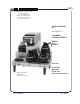
605 BLOOMFIELD INDUSTRIES 10 Sunnen Drive St. Louis, MO 63143 telephone: 800-807-9054 fax: 314-781-2714 www.wellsbloomfield.com OWNERS MANUAL for INTEGRITY™ 5-WARMER COFFEE BREWERS MODEL: 8752 8752KFT Includes: Model 8752 Brewer with optional 8900-Series Decanters Installation Operation Use & Care Servicing Instructions p/n DD-70988 Rev.
WARRANTY STATEMENT All electrical equipment manufactured by WELLS BLOOMFIELD is warranted against defects in materials and workmanship for a period of one year from the date of original installation or eighteen (18) months from the date of shipment from our factory, whichever comes first, and is for the benefit of the original purchaser, except that: a. airpots carry a 30 day parts warranty only. b. dispensers; i.e., tea and coffee carry a 90 days parts warranty only, decanters excluded.
TABLE OF CONTENTS WARRANTY STATEMENT SPECIFICATIONS FEATURES & OPERATING CONTROLS PRECAUTIONS & GENERAL INFORMATION AGENCY LISTING INFORMATION INSTALLATION INSTRUCTIONS OPERATION BREWING COFFEE CLEANING INSTRUCTIONS TROUBLESHOOTING SUGGESTIONS SERVICING INSTRUCTIONS Deliming Instructions EXPLODED VIEW & PARTS LIST WIRING DIAGRAMS xi 1 2 3 3 4 6 8 9 10 11 16 18 23 Thank You for purchasing this Wells Bloomfield appliance.
605 p/n 2M-70988 8752 Owmers Manual FEATURES AND OPERATING CONTROLS IL1636 Fig.
PRECAUTIONS AND GENERAL INFORMATION WARNING: Electric Shock Hazard All servicing requiring access to non-insulated components must be performed by qualified service personnel. Do not open any access panels which require the use of tools. Failure to heed this warning can result in electrical shock. WARNING: Injury Hazard All installation procedures must be performed by qualified personnel with full knowledge of all applicable electrical and plumbing codes.
INSTALLATION READ THIS CAREFULLY BEFORE STARTING THE INSTALLATION REFER TO EXPLODED VIEWS for COMPONENT NAMES/ NUMBERS Unpack the unit. Inspect all components for completeness and condition. Ensure that all packing materials have been removed from the unit. Verify that the Spray Head Gasket and Spray Disk are properly installed. CAUTION: LEVELING THE UNIT EQUIPMENT Damage Verify that provided adjustable legs are installed at each corner of the brewer.
INSTALLATION (continued) A water shut-off valve should be installed on the incoming water line in a convenient location (Use a low restriction type valve, such as a 1/4-turn ball valve, to avoid loss of water flow thru the valve. NSF requires that the brewer be able to be moved for cleaning underneath. A flex line or loops of copper tubing will satisfy this requirement. See Figure 2 below. COPPER LOOPS OR FLEX LINES (PROVIDED BY PLUMBER) WATER INLET FITTING FLOW IL1652 Fig.
OPERATION IL1653 Fig. 4 Brewer Operation Diagram START-UP For initial start-up, or if the brewer has not been used for an extended period of time: • Be sure spray disk and brew gasket are properly installed in the brew head. • Be sure the water supply is properly connected and the water supply valve is turned ON. • Be sure the WATER TANK IS FILLED BEFORE connecting brewer to electrical power the water tank must be filled. Place an empty decanter under the brew head.
OPERATION (continued) Water temperature is sensed by a thermobulb inserted into the water tank. This temperature signal is fed to the thermostat, which controls line power to the heating element. HI-LIMIT THERMOSTAT THERMOBULB The setpoint temperature is adjustable at the thermostat. The element is protected from overtemperature by a hi-limit thermostat. HEATER ELEMENT THERMOSTAT Fig.
BREWING COFFEE CAUTION: Burn Hazard Exposed surfaces of the brewer, brew chamber and decanter may be HOT to the touch, and can cause serious burns. CAUTION: Burn Hazard To avoid splashing or overflowing hot liquids, ALWAYS place an empty decanter under the brew chamber before starting the brew cycle. Failure to comply can cause serious burns. CAUTION: Burn Hazard After a brew cycle, brew chamber contents are HOT. Remove the brew chamber and dispose of used grounds with care.
CLEANING INSTRUCTIONS PROCEDURE: Clean Coffee Brewer CAUTION: PRECAUTIONS: Disconnect brewer from electric power. Allow brewer to cool. FREQUENCY: Daily TOOLS: Mild Detergent, Clean Soft Cloth or Sponge Bristle Brush, Bottle Brush Burn Hazard Brewing and serving temperatures of coffee are extremely hot. Hot coffee will cause serious skin burns. CAUTION: Shock Hazard 1. Disconnect brewer from electric power. Allow brewer to cool before cleaning. Do not submerge or immerse brewer in water. 2.
SYMPTOM Water won’t heat Trips hi-limit safety at start-up Coffee level low (pour-over) Coffee level too high or low (automatic) Brew chamber overflows Sprays water from brew head incorrectly No brew (automatic) No flow from hot water faucet POSSIBLE CAUSE SUGGESTED REMEDY Brewer unplugged or circuit breaker tripped Check power supply cord Check / reset circuit breaker Thermostat set too low Set for desired temperature Hi-Limit thermostat tripped Allow to cool, Reset hi-limit Damaged internal
SERVICING INSTRUCTIONS ACCESS PANELS CAUTION: TOP PANEL: Remove top panel to access hot water tank, thermostat, heating elements, brew circuit tubing and faucet tubing. Top panel is held by two screws at the front and a retaining lip at the rear. FRONT PANELS: Remove upper front panel to access timer and hi-limit. Remove button plugs for simple adjustments or reset. Upper front panel is held by two screws at the bottom and a retaining lip at the top.
SERVICING INSTRUCTIONS (continued) CAUTION: SHOCK HAZARD These procedures involve exposed electrical circuits. These procedures are to be performed by qualified technical personnel only. NOTE: Optimum brewing temperature range is 195ºF to 205ºF (90ºC to 96ºC). IMPORTANT: A mechanical thermostat will maintain temperature within ±5ºF. To prevent boiling water in the brewer, thermostat should be adjusted to a maximum temperature equal to the local boiling temperature minus 5ºF.
SERVICING INSTRUCTIONS (continued) TIMER ADJUSTMENT The amount of water dispensed automatically during a brew cycle is controlled by the timer. Place empty decanter under brew chamber. Press BREW button. Brewer should dispense one decanter of water. To adjust amount: Remove brew chamber and button plug. Adjust knob on timer; clockwise increases time. Run several cycles to check amount of water delivered. Replace button plug. IMPORTANT: Water pressure must be between 20 p.s.i and 90 p.s.i. flowing pressure.
SERVICING INSTRUCTIONS (continued) IMPORTANT: When replacing heating element, also replace seal gaskets. REPLACE HEATING ELEMENT Remove tank lid assembly as described on page 13. Remove two hex nuts holding element to cover. Pull element from mounting holes. Reassemble in reverse order. REPLACE SOLENOID Symptom: Automatic brewer will not flow water; or, automatic brewer drips continuously from brew head. NOTE: Wrench p/n 86660 is designed to allow easy removal of the hoses from the plastic solenoid valve.
SERVICING INSTRUCTIONS (continued) REPLACE TIMER ASSEMBLY Unplug power cord or turn circuit breaker OFF. Remove front panel. Remove knob and three screws holding timer to bracket. Disconnect wiring to timer. Reassemble in reverse order. Adjust timer as described on page 13 REPLACE HOT WATER FAUCET COIL Symptom: Brewer drips continuously from brew head, except when faucet valve is turned OFF. IMPORTANT: When replacing water faucet coil, also replace seal gaskets. Remove tank lid assembly per above.
SERVICING INSTRUCTIONS (continued) CHEMICAL BURN HAZARD Deliming chemicals may be caustic. Wear appropriate protective gloves and goggles during this procedure. Never siphon deliming chemicals or solutions by mouth. This operation should only be performed by qualified and experienced service personnel. IMPORTANT: DO NOT spill, splash or pour water or deliming solution into or over any internal component other than the inside of the water tank.
EXPLODED VIEW & PARTS LIST HOT WATER TANK ASSEMBLY 605 p/n 2M-70988 8752 Owmers Manual IL1658 ITEM PART NUMBER DESCRIPTION 13 8043-5 HOLD-DOWN STRAP 14 8942-92 NUT 8-32 HEX KEPS 50 8512-51 86280 THERMOSTAT (BLACK BODY - INCL. SEAL & MOUNTING SCREWS) THERMO (ALT) (GRAY BODY - INCL.
EXPLODED VIEW & PARTS LIST (continued) CABINET PLUMBING COMPONENTS ITEM PART NO.
EXPLODED VIEW & PARTS LIST ELECTRICAL COMPONENTS 605 p/n 2M-70988 8752 Owmers Manual IL1670 ITEM PART NUMBER DESCRIPTION 2 8572-18 ELEMENT, WARMER 120V 100W 30 8707-55 SWITCH, BREW (MOMENTARY) 31 8528-40 SWITCH, TANK HEATER 240V 20A 32 8738-2 INDICATOR LIGHT 120V GREEN 35 8718-1 TIMER W/KNOB 2-MIN 36 8552-18 TERMINAL BLOCK 4P 39 86945 SWITCH, WARMER 45 85685 SOLENOID 120V W/ BYPASS .
EXPLODED VIEW & PARTS LIST (continued) CABINET ASSEMBLY IL1672 ITEM PART NUMBER DESCRIPTION 1 8700-16 PLATE, WARMER COVER 4 8543-80 CLIP, MOUNTING BUSHING, HEYCO 1/78 23 33 8543-42 GASKET, SPRAYHEAD 34 82727 SPRAY DISK, EMBOSSED 34a 8543-85 RETAINER, SPRAY DISK (DRILL & RIVET REQUIRED TO INSTALL) 35 85089 DOOR, SOLENOID 48 8516-150 81732 LEG SET, BLACK PLASTIC (pk 4) LEG ASSY 1” (OPTIONAL) 70 8706-75 BUTTON PLUG, 2” 102 8542-6 COVER, BASIN TOP (INCLUDES 86666 POUR-OVER ASSY)
605 p/n 2M-70988 8752 Owmers Manual WIRING DIAGRAM 22
10 SUNNEN DRIVE, P.O. BOX 430129, St. Louis, MO 63143 telephone: 314-781-2777 fax: 314-781-2714 www.wellsbloomfield.