
Installation & Operation Instructions

WIRELESS LINKING (PAIRING)
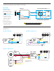
Linking a wireless power pack to a wireless sensor or remote wall station is quickly done via the following procedure:
Step 1. Enter pairing mode by holding down the power pack’s button for 3 seconds until the LED starts alternating white then blue, then release.
Step 2. At the sensor or remote wall station, hold down the programming button for 3 seconds until the LED starts alternating white then blue. Releasing will link the sensor with
any wireless power packs in pairing mode (see note 1 below).
Step 3. Repeat step 2 to link additional sensors or switches.
Step 4. When all devices have been linked, exit pairing mode on the power pack by pressing the button 1 time. Pairing will also be automatically closed after 15 minutes of no
new devices being linked.
Note 1: When in pairing mode, the alternating LED colors on the power pack will periodically pause and blink out the total number of linked devices. There will be no blinks during the
pause until the rst device is linked.
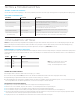
STEP 1
POWER PACK
STEP 2 & STEP 3
WIRELESS SENSORS & REMOTE SWITCHES
STEP 4
POWER PACK
HOLD
FOR 3 SEC
SWX-950
HOLD
FOR 3 SEC
SWX-950
PRESS ONCE
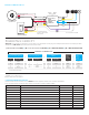
ADDITIONAL APPLICATION INFORMATION
à For areas such as stairwells, the SWX-950-D2 unit can be used to achieve Partial Off operation where lighting is at the full bright level when occupied and dropped to the 50% (level
is congurable) during unoccupied periods.
à Partial On operation can be achieved by the SWX-950-D2 unit. In this conguration 0-10V lighting is turned on to a congurable Partial On Level when triggered from an occupancy
sensor or switch. Lighting can then be adjusted to any level via a wirelessly linked SWX-854-B remote dimmer. Alternatively, if the ON button is pushed on a wirelessly linked
SWX-852-B or SWX-854-B remote switch, lighting will be stepped up to 100% (level is user congurable). Lighting can be turned off manually via an OFF switch press on either the
SWX-852-B, SWX-854-B wireless remote switch (or single button push on a SWX-851 switch controller).
à Congurable dimming parameters include Turn On / Partial On Level, Turn Off Scheme, Fade On/Fade Off Rates, and High/Low Dimming Trim Levels.
à A model SWX-801-xx wired momentary switch can be wired to a SWX-950-AX-D2 model power pack to trigger the 3 step sequence of operation (i.e. Partial On, Full On, Off ). Other
manufacturer’s switches may also be utilized.
à A SWX-950-AX or SWX-950-AX-D2 power pack wirelessly retransmit any switch signals received on its brown input wire (typically from a SWX-801 or SWX-803 momentary switch
or a low voltage wall switch sensor). To receive the retransmitted switch signals, a remote load controller (i.e. another SWX-950 power pack or SWX-851 wall switch controller) will
need to be linked to the transmitting power pack.
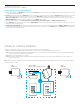
APPLICATIONS (CONT.)