
Installation & Operation Instructions

CONFIGURATION SETTINGS (CONT.)
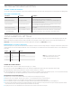
FUNCTION #4 TURN ON / PARTIAL ON LEVEL)
The level the dimming output is set to upon initially turning on (requires unit be in a Partial
On operating mode).
SETTING # VALUES NOTES
2 100%
3 Last User Level (default) Invalid if Operational Mode set to Partial Off.
4 ~30%
Actual voltage value is calculated as the % of
voltage range between high and low trim levels.
Light output at each voltage level depends on
driver/ballast and luminaire.
5 ~40%*
6 ~50%
7 ~60%
8 ~70%
9 ~80%
FUNCTION #5 TURN OFF SCHEME
The actions of the power pack’s dimming output and relay when an unoccupied signal or
an off switch press is received.
SETTING # VALUES NOTES
2 Drop to Off*
Dimming output drops to low trim and relay opens
(*default)
3 Fade to Off Dimming output fades to low trim and relay opens
4 Fade to 0V
Dimming output fades to 0 volts (e.g. below a connected
driver’s electronic off level). Relay remains closed.
5 Fade to Low Trim
Dimming output fades down to low trim level. Relay remains
closed.
6 Drop to Low Trim
Dimming output drops down to low trim level. Relay remains
closed.
7 Drop to OV
Dimming output drops to 0 volts (e.g. below a connected
driver’s electronic off level). Relay remains closed.
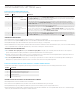
FUNCTION #6 HIGH TRIM
The voltage of the dimming output at the full bright level (step).
SETTING # VALUES NOTES
2 10 VDC (100%) * *default
Exact light output % at each voltage
level depends on driver/ballast and
luminaire.
3 9 VDC (90%)
4 8 VDC (80%)
5 7 VDC (70%)
6 6 VDC (60%)
7 5 VDC (50%)
FUNCTION #7 LOW TRIM
The voltage to which the dimming output will drop when the unit is in the off state. This
setting is only active when the unit’s Turn Off Scheme is set to Dim to Low Trim.
SETTING # VALUES NOTES
2 0 VDC
Exact light output % at each voltage
level depends on driver/ballast and
luminaire.
3 1 VDC (10%)
4 2 VDC (20%)
5 3 VDC (30%)* *default
6 4 VDC (40%)
7 5 VDC (50%)
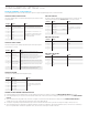
FUNCTION #9 FADE OFF TIME
SETTING # VALUES NOTES
2 0.75 Sec
3 1.5 Sec* *default
4 3 Sec
5 5 Sec
6 15 Sec
FUNCTION #10 FADE ON TIME
SETTING # VALUES NOTES
2 0.75 Sec
3 1.5 Sec* *default
4 3 Sec
5 5 Sec
6 15 Sec
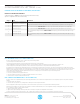
DETAILED DIMMING CONFIGURATION
Several dimming parameters (listed in the tables below) can be adjusted. A step-by-step programming procedure is listed below the tables.
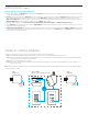
CHANGING A DETAILED DIMMING CONFIGURATION SETTING
1 From the below tables of detailed dimming functions, note the number (#) of the function to be modied. For example, the TURN ON /PARTIAL ON LEVEL function is #4.
2 To enter programming mode, press and release the unit’s button the number of times of the chosen function. For example, press the button 4 times to access the TURN ON /PARTIAL
ON LEVEL.
3 The LED will ash back the setting number of the current value as it appears in each function’s detailed table below. For example, the default TURN ON /PARTIAL ON LEVEL is
setting #3, Last User Level). Continue to the next step before the current setting is blinked back 3x).
4 To change the setting number, interrupt the blink back and press and release the button the number of times equal to the new setting #. For example, 3 times (for 3V, ~30%).
5 The LED will ash back the new setting number as conrmation and will be saved after three conrmations. After the third conrmation sequence, a successful save is indicated by a
two sets of rapid White ashes. If the Blue LED rapid ashes twice, save was unsuccessful and process should be started over.