AutoStop TM BX8894 BX88100 OPERATOR, PARTS & INSTALLATION MANUAL BX8894, BX88100 AutoStopTM TOWING PRODUCTS DIVISION
REQUIREMENTS REQUIREMENTS FOR PROPER OPERATION A. You must have a two (2) inch square receiver type hitch on your towing vehicle that aligns within two (2) inches of the height of the tow bar. NOTE: The tow bar may slope upward toward the towing vehicle, but should not slope downward toward the towing vehicle. The AutoStop needs a level push on the ball mount tube to operate properly. This requires that the height of the receiver tube be adjusted rather than the height of the ball as happens normally.
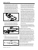
INSTALLATION 3. Should dash light activate while turning, corrective action must be taken. "STOP" the RV to investigate. a. If readjustment of cable is needed, this is usually an indication that the cable is too Figure 6 tight or is hanging up on one of the towing components. MECHANICAL INSTALLATION 1. Insert the AutoStop into the receiver tube with the actuating cable on the drivers side of the opening. (Figure 6) Align the holes and insert the cross pin and safety clip (or locking pin).
INSTALLATION 7. When alignment is correct, enlarge the pilot hole with a 5/16 inch bit. Cut a slit in the carpet to correspond to the hole in the floor. Feed the cable housing through the carpet and hole in the floor following your selected route as mentioned above. When installed properly, the nylon thumb nut should be showing on top of the carpet. Avoid abrupt bends in the cable housing as this will cause friction and premature wear of the cable.
INSTALLATION / MAINTENANCE depressed by the AutoStop. To keep this from happening we have included electrical parts with the kit to automatically disconnect the brake lights when the key is off. The only change you will notice to the towed vehicle is that the brake lights on the car will only be activated by the brake pedal when the ignition is in the "on" position.
DISASSEMBLY / ASSEMBLY INSTRUCTIONS Figure 10 spade terminal on the other. Put the ring terminal under the head of the bolt and the spade terminal on the male terminal on the switch labeled “2”. NOTE: The terminal marked “1” will not be used. 10. Gather up the wires and the relay. Anchor them up out of the way so they will not interfere with driving the vehicle.
5. Clean all parts with a mild solvent such as WD-40 and be sure to dry all parts thoroughly. Use a brush to insure the inside of the AutoStop tube is clean as well. ASSEMBLY INSTRUCTIONS 1. Slide the cable assembly back into the AutoStop tube and secure the cable clamp with the round head screw and hex nut. (Figure 11) Leave approximately one inch of cable sheathing extending outside of the AutoStop tube. NOTE: As described earlier on page 1, your AutoStop can be configured to give a 2 inch rise.
ASSEMBLY / ADJUSTING INSTRUCTIONS Figure 18 vertical, to keep the cable from jumping between Suggested initial preload ranges are: pulleys. 1/4" - Towed vehicle under 2,000 lbs. 1/2" - 2,000 to 3,500 lbs. 6. Set the wide pulley on top of the pulley divider. It 3/4" - 3,500 to 5,000 lbs. is symetrical so it can be put on either way. (Figure 1" - Maximum preload 16) Set the cable anchor on top of the wide pulley with the groove facing you and the notch out of the corner to your right. (Figure 17) 7.
ASSEMBLY INSTRUCTIONS 5/8 rod. initial setting, adjust to your driving preference if needed. The location of the adjusting nut is shown in Figure 23. The initial preload ranges are listed in Figure 24. 10. Once you have the cable wrapped properly, pull slowly on the other end of the cable while holding the pulleys and swage in place with the other hand to prevent the cable from unwrapping. Keep tension on the cable and slide the pulleys into the AutoStop tube.
REPLACEMENT PARTS CABLE ROUTING 292-2215 7/02 9 of 10
REPLACEMENT PARTS Ref. No. 1 2 3 4 5 6 7 8 9 10 11 12 13 14 15 16 17 18 19 20 21 22 Qty. 1 1 1 1 1 1 2 1 1 1 1 1 1 1 1 1 1 1 1 1 1 1 Parts not shown: Ref. No. 23 24 25 26 27 28 29 30 31 32 33 34 35 36 37 38 39 40 41 42 43 44 45 Qty. 2 1 1 3 3 3 1 2 3 8 1 1 1 1 1 4 2 1 1 1 1 1 1 Part No. Parts List Description 62-3161............................................................................... Receiver Cable Assembly 202-0047..........................................................................
TO BE VALID, WARRANTY CARD MUST BE COMPLETED IN ITS ENTIRETY BY AN AUTHORIZED DISTRIBUTOR OR DEALER AND SENT TO AUTOMATIC EQUIPMENT MFG. CO., PENDER, NEBRASKA. FAILURE TO DO SO WILL VOID THE WARRANTY. Product Safety Policy Statement It is, and shall continue to be, a primary objective of Automatic Equipment Manufacturing Company to provide customers with safe and reliable products.