
User Manual

INSTALLATION
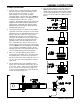
When installed properly, the nylon thumb nut
should be showing on top of the carpet. Avoid
abrupt bends in the cable housing as this will cause
friction and premature wear of the cable. If the
cable housing runs through the bumper or the
bumper skirt, drill a 5/16 inch hole there to align the
cable as previously mentioned with the actuating
cable. The cable housing should protrude a 1/2
inch beyond the bumper, or bumper skirt or where
ever the flag terminal is mounted, pointing directly
at the hitch ball. Retract the cable and cut off any
excess cable housing with side cutters. Fig.25
8. Lubricate the cable with silicon spray and feed the
cable back through the cable housing, and secure
the loop around the brake pedal arm allowing the
cable to feed directly and straight into the cable
housing. Use wire ties or wrap with electrical tape
to insure that the loop around the pedal arm does
not loosen when the brake pedal is being used. If
alignment is proper, the cable will feed into the
cable housing when the brake pedal is depressed.
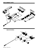
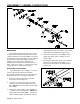
9. Attach the cable thimble into the clevis on the
AutoStop actuating cable with the quick release
pin. (Figure 3 or 4) Run the loose end of the pedal
cable through the clevis and thimble and secure this
loop with the two cable clamps. Place the first
clamp as close as possible to the thimble and the
second cable clamp about four (4) inches from the
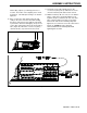
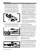
first. Before tightening the clamps adjust the cable
length so there is about four to five (4-5) inches of
vertical play in the cable before the towed vehicle’s
braking lights come on. (Fig. 22) Cut off and
discard any excess cable. Recheck this
adjustment after a short trial run. If the towed
vehicle’s brake lights come on at the slightest touch
of the cable, with the cable properly adjusted, the
brake lights are coming on during pedal free travel.
Most brake light switches are not adjustable, so
install a bungee cord from the pedal to the driver’s
seat base to reduce the free travel movement of the
pedal while towing.
10. Install all other safety and towing equipment as
required. The AutoStop only actuates the towed
vehicles brakes. It does not eliminate the necessity
of safety chains, towing lights, transmission pumps
or driveshaft disconnects.
MECHANICAL INSTALLATION NOTES
In Steps 4 and 7 when routing the housing, do not make
a turn tighter than a four (4) inch radius. If you need to
make a bend in the housing you will need to anchor the
housing in the middle of the bend. There are plastic
cable ties and two clamps and stove bolts included with
the kit. You will also need to anchor the housing as
close as possible to the end that sticks out of the grill of
the car. After you have the housing installed and the
cable inserted, lay under the vehicle and have someone
pull on the cable. When pressure is applied to the
cable the housing will tend to try to “straighten out”
through the bends. If there are several places where
this happens, most of the cable pull will be used up
straightening the housing rather than pulling on the
brake pedal. Note where the housing is trying to
straighten and anchor these areas.
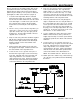
ELECTRICAL INSTALLATION
If the towed vehicle’s brake lights will work with the key
off, there is a possibility that the towed vehicle’s battery
may be drained after towing as the brake lights will be
activated each time the brake pedal is depressed by the
AutoStop. To keep this from happening we have
included electrical parts with the kit to automatically
disconnect the brake lights when the key is off. The
only change you will notice to the towed vehicle is that
the brake lights on the car will only be activated by the
brake pedal when the ignition is in the "on" position.
292-2215 7/02 3 of 10
Figure 8
Figure 22
Figure 25