
User Manual


INSTALLATION
arms are locked in the towing position.
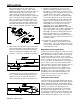
4. Now you are ready to install the brake pedal cable
on the towed vehicle. This cable should run from
the end of the AutoStop actuating cable in a line
about parallel to the bottom plane of the tow bar
coupler, but staying inboard of the driver’s side arm,
probably through the bumper or bumper skirt and up
to the brake pedal through the floor board. Visually
select a route that will not interfere with any moving
components or possibly contact electrical
terminals. Also, make sure cable doesn't come
into contact with any aluminum components, such
as a transmission housing, which could cause
significant wear. Make sure cable route will lead to
the general area where the steering column goes
through the floor.
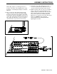
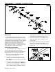
5. From the drivers seat note the distance and
direction from the steering column to the brake
pedal when the brake pedal is fully depressed. This
will normally be a little below and a little inboard of
the steering column. Mark the spot on the carpet
with chalk where the cable should pass through the
floor after making a loop around the brake pedal
arm. (Figure 7) Measure the distance and direction
and confirm that a drilled hole will not interfere with
anything as stated in Step 4. When selecting the
location for the hole, it should be positioned so the
cable is pulling straight away on the brake pedal
arm, not to either side and not up or down. (Figure
7)
6. After you have confirmed that the location for the
hole will not cause any problems, pull the carpet
back and drill a 1/8 inch pilot hole. Allow the drill
bit to just barely break through the metal floor.
Next, inspect where the hole actually is from the
engine compartment side to verify that this location
will not cause problems and to see how the cable
aligns with the brake arm. If the hole needs to be
relocated slightly, redrill and seal the previous hole
with a rivet or sealant.
7. When alignment is correct, enlarge the pilot hole
with a 5/16 inch bit. Cut a slit in the carpet to
correspond to the hole in the floor. Feed the cable
housing through the carpet and hole in the floor
following your selected route as mentioned above.
292-2215 7/02 2 of 10
a. If readjustment of cable is needed, this is
usually an indication that the cable is too
tight or is hanging up on one of the towing
components.
MECHANICAL INSTALLATION
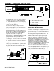
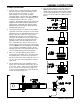
1. Insert the AutoStop into the receiver tube with the
actuating cable on the drivers side of the
opening. (Figure 6) Align the holes and insert the
cross pin and safety clip (or locking pin). If the
receiver tube is open at the front, it must be closed
to keep road dust out of the mechanism. Clean the
area and cover with tape.
2. For coupler style tow bars install a hitch ball of
the matching size for the tow bar coupler, preferably
using a one inch diameter shank and a one inch nut
and lock washer. Do not use a hitch ball that has a
bolt which threads into the ball. For added safety,
it is recommended that after tightening the hitch ball
nut to the required torque, drill the hitch ball nut and
install a cotter key. Note: Be sure tow bar and
Autostop are both parrallel with the ground.
3. Hook up the towed vehicle to the towing vehicle and
gently back the towed vehicle until all the slack is
out of the AutoStop, moving it to its fully extended
towing position. If a self aligning tow bar is
being used, be sure both arms, are fully
extended to the locked towing position. Drive
the towing vehicle forward a few feet if
necessary and pull on the AutoStop actuating
cable to remove all slack. It is very important
that the connecting cables have 4 inches of vertical
slack when in the towing position. This assures the
Autostop will not be active when towing and allows
for turns in either direction. This does not reduce
the effectiveness of the Autostop.
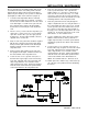
Before the adjustment is made:
(1) Be sure the Autostop is fully retracted to the
towing position. (2) Be sure the cross pin is
inserted through the pulley hole. (3) Be sure both
tow bar arms are fully extended. (4) Be sure both
Figure 7
Figure 6