
User Manual

ASSEMBLY / ADJUSTING INSTRUCTIONS
292-2215 7/02 7 of 10
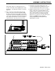
6. Set the wide pulley on top of the pulley divider. It is
symetrical so it can be put on either way. (Figure
16) Set the cable anchor on top of the wide pulley
with the groove facing you and the notch out of the
corner to your right. (Figure 17)
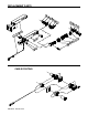
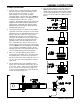
7. Set the movable pulley assembly next to the
AutoStop tube, and next to it place the stationary
pulley assembly.(Figure18) You are now ready to
route the cable around the pulleys.
8. Pull the cable through so you have all the slack at
the back where you will be wrapping the cable. The
AutoStop tube should still be positioned with the
tongue flat side towards you. (Figure 18)
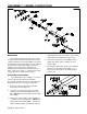
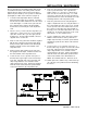
9. Refer to (Figure 19) while wrapping cable around the
pulleys. The cable should protrude from the
AutoStop tube at the lower corner of the tongue flat
side facing you. From here, route the cable in front
of pulley "A" and counterclockwise around pulley
"B". Continue on the back side back to pulley "A"
and go around it counterclockwise also. From here,
route the cable around pulley "C" counterclockwise
then pulley "D" counterclockwise. Lay the cable in
the groove in the cable anchor and set the cable
swage into the notch in the cable anchor.
Figure 18
Figure 19
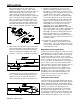
ADJUSTMENT INSTRUCTIONS
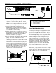
The Autostop "Load Ranger" is equipped with a return
spring and an adjusting nut to set the spring pre-load in
proportion to the weight of the towed vehicle. This pre-
load will not allow the activation of the towed vehicle's
brakes during light braking of the towing vehicle. This
also prevents application of the towed vehicle's brakes
when descending a moderate grade against engine
compression, jake brake or exhaust brake, but still
allows proportional braking when the towing vehicle's
service brakes are applied. Before making any adjust-
ment, drive the rig a few blocks and re-check the
installation for proper cable slack. With a flat blade
screwdriver, rotate the adjusting nut upward with a down
motion of the screwdriver handle to increase the
preload. This will move the nut in the direction of the
towing vehicle, compressing the return spring. Continue
to rotate the adjusting nut to the desired preload. If you
desire the Autostop to activate only during very heavy
braking, adjust to the max. setting. After your
Figure 23
Suggested initial preload ranges are:
1/4" - Towed vehicle under 2,000 lbs.
1/2" - 2,000 to 3,500 lbs.
3/4" - 3,500 to 5,000 lbs.
1" - Maximum preload
Figure 24