
User Manual

INSTALLATION / MAINTENANCE
292-2215 7/02 4 of 10
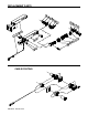
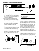
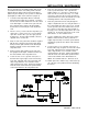
We also include in the kit a lighted switch that should
be installed in the dash of the towing vehicle and will
light up when the brake pedal in the towed vehicle is
pulled on by the AutoStop. If the operator is distracted
by the light, the switch can be turned off. (Figure 9)
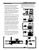
1. Locate the brake light switch which is activated
when the brake pedal is pressed down. Locate the
hot wire into the switch and the wire from the switch
to the brake lights. You will need to splice into the
wire coming from the switch to the brake lights.
Cut the wire at convenient place and strip the two
ends.
2. If there is room, you can locate the relay where you
cut the wires. If there isn’t room, you may want to
splice wire onto the wires you cut to give yourself
working room. The black wire and butt connectors
supplied can be used for this.
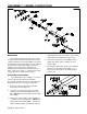
3. Strip one end of the yellow wire and twist it together
with the wire coming from the brake pedal switch.
Crimp a female spade terminal on the twisted pair.
Slide the terminal over the male terminal on the
relay labeled “87”.
4. Crimp a female spade terminal on the end of the
wire going the brake lights. Slide this terminal over
the male terminal on the relay labeled “30”.
5. Locate a bolt to use as a ground. Cut a piece of
the black wire long enough to reach from the relay
to the bolt. Strip both ends of the black wire and
crimp a ring terminal on one end and a female
spade terminal on the other. Put the ring terminal
under the head of the bolt and the spade terminal
on the male terminal on the relay labeled “85”.
Figure 9
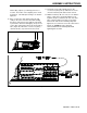
6. In the car's fuse panel or another convenient place,
locate a power wire that is "hot" only when the
ignition switch is on. Cut a piece of black wire to
reach from the "hot" wire to the relay. Use a butt
connector to splice into the "hot" wire and crimp a
spade terminal on the other end and slide it over the
remaining terminal on the relay labeled "86".
7. Route the yellow wire from the relay through the
engine compartment of the car, along the bottom of
the coach and into the dash of the coach. You will
need to provide a disconnect between the car and
the coach if you don’t have any extra terminals in
the plug you are currently using between the coach
and the car. Tie the wire to the frame of the coach
with cable ties or other suitable means.
8. Locate a suitable place in the dash for the switch.
With the switch mounted, cut the yellow wire to
length, strip and crimp on a female spade terminal,
and plug the spade into the switch on the terminal
marked “3”.
9. Locate a bolt to use as a ground. Cut a piece of
the black wire long enough to reach from the switch
to the bolt. Strip both ends of the black wire and
crimp a ring terminal on one end and a female
spade terminal on the other. Put the ring terminal
under the head of the bolt and the spade terminal
on the male terminal on the switch labeled “2”.
NOTE: The terminal marked “1” will not be used.
10. Gather up the wires and the relay. Anchor them up
out of the way so they will not interfere with driving
the vehicle.