TW120 ROTARY CUTTER Published 01/11 Part NO. 00762120C OPERATOR’S MANUAL This Operator's Manual is an integral part of the safe operation of this machine and must be maintained with the unit at all times. READ, UNDERSTAND, and FOLLOW the Safety and Operation Instructions contained in this manual before operating the equipment. C01Cover RHINO ® 1020 S. Sangamon Ave. Gibson City, IL 60936 800-446-5158 E-mail: parts@servis-rhino.com ©2011 Alamo Group Inc. $0.
To the Owner/Operator/Dealer This Operator's Manual is an integral part of the safe operation of this machine and must be maintained with the implement at all times. A Manual canister is provided on the implement where this manual can be properly stored. If you lose or damage this manual a free replacement manual can be obtained from an authorized Rhino dealer or by down loading the manual from the Rhino website www.servis-rhino.
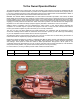
In order to reduce accidents and enhance the safe operation of mowers, Alamo Group Ag Division, in cooperation with other industry manufacturers has developed the AEM/FEMA Industrial and Agricultural Mower Safety Practices video and guide book. The video will familiarize and instruct mower-tractor operators in safe practices when using industrial and agricultural mowing equipment.
Alamo Group Ag.
DEALER to CUSTOMER Pre-Delivery/ Operation Instructions Dealer should inform the Purchaser of this product of Warranty terms, provisions, and procedures that are applicable. Dealer should inform Purchaser to review the contents of the Operator’s Manual including safety equipment, safe operation and maintenance, to review the Safety Signs on the implement (and tractor if possible) and of Purchaser’s responsibility to train his/her operators’s of safe operation procedures.
Table of Contents SAFETY SECTION ............................................................................................................. 1-1 GENERAL SAFETY INSTRUCTIONS AND PRACTICES ................................................................................ 1-2 OPERATOR SAFETY ....................................................................................................................................... 1-3 CONNECTION OR DISCONNECTING IMPLEMENT SAFETY .....................................
ROPS and Seat Belt ......................................................................................................................................... 4-4 Tractor Safety Devices ...................................................................................................................................... 4-5 Tractor Horsepower .......................................................................................................................................... 4-5 3-Point Hitch .............
MAIN CV DRIVELINE SAFETY SHIELD (FIGURE Mnt-R-0032) ..................................................................... 5-9 DRIVELINE TAPER CONE YOKE REMOVAL INSTRUCTIONS ................................................................... 5-10 BLADE SERVICING ....................................................................................................................................... 5-10 BLADE SHARPENING ............................................................................................
SAFETY SECTION Safety Section 1-1 © 2011 Alamo Group Inc.
SAFETY GENERAL SAFETY INSTRUCTIONS AND PRACTICES SAFETY A careful operator is the best operator. Safety is of primary importance to the manufacturer and should be to the owner/operator. Most accidents can be avoided by being aware of your equipment, your surroundings, and observing certain precautions. The first section of this manual includes a list of Safety Messages that, if followed, will help protect the operator and bystanders from injury or death.
SAFETY OPERATOR SAFETY • • • • • • • • READ, UNDERSTAND and FOLLOW Operator's Manual instructions, Warnings and Safety Messages. WEAR SAFETY GLASSES, safety shoes, hard hat, hearing protection and gloves when operating or repairing equipment WEAR appropriate breathing respirator when operating in dusty conditions to avoid respiratory diseases. DO NOT WEAR loose clothing or jewelry to avoid rotating parts entanglement injury. DO NOT USE DRUGS or ALCOHOL before or while operating equipment.
SAFETY SAFETY CONNECTION OR DISCONNECTING IMPLEMENT SAFETY TO AVOID SERIOUS INJURY OR DEATH FROM BEING CRUSHED BY TRACTOR OR IMPLEMENT: WHEN BACKING tractor to implement hitch: • DO NOT ALLOW BYSTANDERS between tractor and implement BEFORE connecting and disconnecting implement hitch: • STOP TRACTOR ENGINE, place transmission into park, engage parking brake and remove key. WHEN connecting and disconnecting implement hitch: • • • DO NOT crawl or walk under raised mower or wing.
SAFETY CRUSHING HAZARDS • • • • USE ROPS and SEAT BELT equipped tractors for mowing operations. KEEP ROPS lock in up position. ALWAYS BUCKLE UP seat belt when operating tractor and equipment. ONLY OPERATE tractor and equipment while seated in tractor seat. WHEN RAISING OR LOWERING IMPLEMENT: • • • Raise or lower ONLY WHILE SEATED in tractor seat with seat belt buckled. Raise or lower ONLY when implement tongue is securely attached to tractor drawbar TO AVOID implement tip over.
SAFETY SAFETY THROWN OBJECTS HAZARDS ROTARY MOWERS CAN THROW OBJECTS 300 FEET OR MORE UNDER ADVERSE CONDITIONS. TO AVOID SERIOUS INJURY OR DEATH TO OPERATOR OR BYSTANDERS FROM THROWN OBJECTS: • KEEP bystanders 300 feet away STOP MOWING IF PASSERSBY ARE WITHIN 300 FEET UNLESS: • • • • All THROWN OBJECT SHIELDING including, Front and Rear Deflectors, Chains Guards, Steel Guards, Bands, Side Skirts and Skid Shoes in place and in good condition when mowing.
SAFETY THROWN OBJECTS HAZARDS (CONTINUED) • DO NOT exceed mower's rated Cutting Capacity or cut non-vegetative material. • USE ENCLOSED TRACTOR CABS when two or more mowers are operating in mowing area. • ADJUST mower sections or wing close and parallel to ground without exposing blades • ADJUST cutting HEIGHT to AVOID BLADE CONTACT with solid objects like wire, rocks, posts, curbs, guard rails and fixed obstructions.
SAFETY SAFETY RUN OVER HAZARDS TO AVOID SERIOUS INJURY OR DEATH FROM FALLING OFF TRACTOR OR EQUIPMENT RUN OVER: • USE ROPS and SEAT BELT equipped tractors for mowing operations. • KEEP ROPS locked in UP position. • ONLY start tractor while seated in tractor seat. • ALWAYS BUCKLE UP seat belt when operating tractor and equipment. • ONLY OPERATE tractor and equipment while seated in tractor seat. • NEVER ALLOW RIDERS on tractor or implement.
SAFETY PTO ENTANGLEMENT HAZARDS STAY AWAY and KEEP hands, feet and body AWAY from rotating blades, drivelines and parts until all moving elements have stopped. • STOP, LOOK and LISTEN before approaching the mower to make sure all rotating motion has stopped. • ROTATING COMPONENTS CONTINUE to ROTATE after the PTO is shut off.
SAFETY SAFETY MOWER BLADE CONTACT HAZARDS KEEP AWAY FROM ROTATING BLADES TO AVOID SERIOUS INJURY OR DEATH FROM BLADE CONTACT: • • • • STAY AWAY and KEEP HANDS, FEET and BODY AWAY from rotating blades, drivelines and parts until all moving elements have stopped. DO NOT put hands or feet under mower decks STOP rotating BLADES disengage PTO and wait for blade to stop rotating before raising mower deck or wings STOP LOOK and LISTEN before approaching the mower to make sure all rotating motion has stopped.
SAFETY HIGH PRESSURE OIL LEAK HAZARDS • • DO NOT OPERATE equipment with oil or fuel leaks. KEEP all hydraulic hoses, lines and connections in GOOD CONDITION and TIGHT before applying system pressure. • RELIEVE HYDRAULIC PRESSURE before disconnecting lines or working on the system. • REMOVE and replace hose if you suspect it leaks. Have dealer test it for leaks. HIGH PRESSURE FLUID LEAKS CAN BE INVISIBLE.
SAFETY SAFETY ELECTRICAL & FIRE HAZARDS TO AVOID SERIOUS INJURY OR DEATH FROM ELECTRICAL CONTACT WHEN WORKING AROUND ELECTRICAL POWER LINES, GAS LINES AND UTILITY LINES: • INSPECT mowing area for overhead or underground electrical power lines, obstructions, gas lines, cables and Utility, Municipal, or other type structure. • DO NOT allow mower to contact with any Utility, Municipal, or type of structures and obstructions. • CALL 811 and 1-800-258-0808 for identify buried utility lines.
SAFETY TRANSPORTING HAZARDS • KEEP transport speed BELOW 20 mph to maintain control of equipment. • REDUCE SPEED on inclines, on turns and in poor towing conditions. • DO NOT TOW with trucks or other vehicles • USE only properly sized and equipped tractor for towing equipment. • FOLLOW all local traffic regulations. TRACTOR REQUIREMENTS FOR TOWING OR TRANSPORTING IMPLEMENTS: • ONLY TRANSPORT with tractor with ROPS in the raised position.
SAFETY SAFETY HAZARDS WITH MAINTENANCE OF IMPLEMENT AVOID SERIOUS INJURY OR DEATH FROM COMPONENT FAILURE BY KEEPING IMPLEMENT IN GOOD OPERATING CONDITION IN PERFORMING PROPER SERVICE, REPAIRS AND MAINTENANCE. BEFORE PERFORMING SERVICE, REPAIRS AND MAINTENANCE ON THE IMPLEMENT: • STOP ENGINE AND PTO, engage parking brake, lower implement, allow all moving parts to stop and remove key before dismounting from tractor. • PLACE implement on ground or securely block up raised equipment.
SAFETY PARTS INFORMATION PARTS INFORMATION Rhino mowers use balanced and matched system components for blade carriers, blades, cuttershafts, knives, knife hangers, rollers, drivetrain components, and bearings. These parts are made and tested to Rhino specifications. Non-genuine "will fit" parts do not consistently meet these specifications. The use of “will fit” parts may reduce mower performance, void warranties, and present a safety hazard. Use genuine Rhino mower parts for economy and safety.
SAFETY Decal Location - Lift Type SAFETY NOTE: Rhino supplies safety decals on this product to promote safe operation. Damage to the decals may occur while in shipping, use, or reconditioning. Rhino cares about the safety of its customers, operators, and bystanders, and will replace the safety decals on this product in the field, free of charge (Some shipping and handling charges may apply). Contact your Rhino dealer to order replacement decals. TW120 01/11 © 2011 Alamo Group Inc.
SAFETY PART NO. QTY LEVEL DESCRIPTION 1. 2. 3. 4. 5. 6. 7. 8. 9. 10. 11. 12. 13. 14. 15. 16. 17. 18. 19. 20. 21. 22. 23. 24. 25. 26. 27. 28.
SAFETY Decal Location - Pull Type SAFETY NOTE: Rhino supplies safety decals on this product to promote safe operation. Damage to the decals may occur while in shipping, use, or reconditioning. Rhino cares about the safety of its customers, operators, and bystanders, and will replace the safety decals on this product in the field, free of charge (Some shipping and handling charges may apply). Contact your Rhino dealer to order replacement decals. TW120 01/11 © 2011 Alamo Group Inc.
SAFETY ITEM D389 D390 D388 00756004 00756005 D137 D138 D454 00771283 99102 00787406 00785891 00785892 D302 03200347 00760657 nfs D401 1458392 1458393 00776031 00762120C 10058000 00024100 02959924 D614 D534 D629 D518 D608 QTY 1 1 1 3 2** 1 1 1 3 1 2 2 1 2 1 1 1 1 2 2 1 1 3 6 3 3 2 1 1 2 * Provided by Tractor Manufacturer () Provided by Driveline Manufacturer LEVEL DECAL DECAL DECAL DANGER DANGER INSTRUCT INSTRUCT WARNING INSTRUCT NAME NAME NAME NAME LOGO REFLECTOR IMPORTANT SER PLT INSTRUCT REFLECTOR
SAFETY SAFETY Decal Description TW120 01/11 © 2011 Alamo Group Inc.
SAFETY SAFETY TW120 01/11 © 2011 Alamo Group Inc.
SAFETY SAFETY TW120 01/11 © 2011 Alamo Group Inc.
SAFETY SAFETY TW120 01/11 © 2011 Alamo Group Inc.
SAFETY SAFETY TW120 01/11 © 2011 Alamo Group Inc.
SAFETY SAFETY TW120 01/11 © 2011 Alamo Group Inc.
SAFETY SAFETY TW120 01/11 © 2011 Alamo Group Inc.
SAFETY SAFETY TW120 01/11 © 2011 Alamo Group Inc.
SAFETY SAFETY TW120 01/11 © 2011 Alamo Group Inc.
SAFETY Federal Laws and Regulations This section is intended to explain in broad terms the concept and effect of federal laws and regulations concerning employer and employee equipment operators. This section is not intended as a legal interpretation of the law and should not be considered as such. Employer-Employee Operator Regulations U.S. Public Law 91-596 (The Williams-Steiger Occupational and Health Act of 1970) OSHA Title 29, Code of Federal Regulations Part 1928.57(a)(6). www.osha.
Contents Acknowledgment . . . . . . . . . . . . . . . . . . . . . . . . . . . . . . 2 Foreword . . . . . . . . . . . . . . . . . . . . . . . . . . . . . . . . . . . . . 2 Safety Alerts. . . . . . . . . . . . . . . . . . . . . . . . . . . . . . . . . . . 3 A Word To The User/Operator . . . . . . . . . . . . . . . . . . . . 3 The Industrial/Agricultural Mower. . . . . . . . . . . . . . . . . 4 Follow A Safety Program . . . . . . . . . . . . . . . . . . . . . . . . 5 Prepare For Safe Operation . . . . . . . .
Safety Alerts Symbol Signal Words This Safety Alert Symbol means: “ATTENTION! STAY ALERT! YOUR SAFETY IS INVOLVED!” Signal words are distinctive words that will typically be found on safety signs on the mower and other worksite equipment. These words may also be found in this manual and the manufacturer’s manuals. These words are intended to alert the operator to a hazard and the degree of severity of the hazard.
The Industrial/Agricultural Mower Industrial/Agricultural Mower Types Mowers are used for pasture clipping, crop residue shredding, heavy brush cutting, waterways, right-ofways, roadside or highway mowing. Also, these mowers are used for cutting grass and other growth in public areas such as parks and cemeteries. Flail Boom Rotary Sickle Bar Folding Wing Rotary The Industrial/Agricultural Mower Agricultural Disc Mower Types Disc mowers are designed and equipped to cut hay crops at higher field speed.
Follow A Safety Program Protect Yourself Wear personal protective clothing and Personal Protective Equipment (PPE) issued to you or called for by job conditions. You must ALWAYS wear safety glasses with side shields. You may also need: — Hard hat — Safety shoes — Safety goggles or face shield — Heavy gloves — Hearing protection — Reflective clothing — Wet weather gear — Respirator or filter mask Wear whatever is needed—don’t take chances.
Follow A Safety Program Avoid Injury From Raised Equipment Avoid Injury From High Pressure Fluid Avoid possible crushing injury from falling mower or other raised equipment. Avoid fluid injection injury due to high pressure fluid leaks. Avoid Crushing – Block Up or Securely Support Mower Before working near or under raised mower or equipment parts: — Securely support or block up raised mower or equipment parts according to the operator’s manual.
Follow A Safety Program Be Alert! For Safe Operation Know where to get assistance. Know how to use a first aid kit and fire extinguisher/fire suppression system. You must be a qualified and authorized operator for proper operation of your machine. You must clearly understand the written instructions supplied by the manufacturer, be trained—including actual operation of the mower—and know the safety rules and regulations for the worksite.
Follow A Safety Program Some Rules You Must Work By (continued) Keep Children Away from Equipment — Only qualified and authorized individuals may operate this equipment. — Never allow children to play on, ride on or operate the equipment. Children are not qualified to operate this equipment. — Do not allow any riders. — Use three-point contact (handholds and steps) and face the equipment when mounting or dismounting. — Keep bystanders 300 ft (92 m) from the mowing operation.
Prepare For Safe Operation Check The Mower And Tractor Equipment Before beginning your work day inspect the machine and have all systems in good operational condition. Walk-Around Inspection WARNING! Prevent possible crushing injury from falling equipment. Hydraulic system or part failure could cause unsupported equipment to fall. Do not go under raised equipment unless it is properly supported according to the operator’s manual.
Prepare For Safe Operation Know The Work Area Before you operate the mower thoroughly inspect the work area. Walk around the area and inspect the surfaces you will travel on when using the mower.
Prepare For Safe Operation Tractor And Mower Controls Safety Test Start the tractor following the specific procedures in the manufacturer’s operator’s manual. These procedures normally include: — Fasten and adjust seat belt on your ROPS-equipped tractor. — Check parking brake for engagement. — Check PTO disengagement. — Check all controls for Park position. — Warn others in area before starting tractor. — Start tractor following tractor manufacturer’s recommended starting procedures.
Prepare For Safe Operation Hitching Mower To Tractor Read and Understand Manuals Before Operating Three-point hitch-mounted mowers: — Refer to mower and tractor manufacturers’ manuals. — Place tractor’s hydraulic power lift (rockshaft) selector lever in down position to avoid unexpected movement. — Explain the hitching procedures to those operators who cannot read. — Front-end weights may be needed to maintain steering control and front-end stability. Refer to the manufacturers' operator's manual(s).
Start Safely Make The Right Start Mow only in daylight or good artificial light conditions. Avoid serious injury or death from mower-thrown objects or blade contact: — Keep chain shields, flexible or solid deflector shields or discharge chutes in place and in good repair. — Keep bystanders at least 300 ft (92 m) from mowing operation. — Never direct mower discharge toward anyone. — Keep hands, feet and other body parts away from rotating parts, blades and discharge openings.
Operate Safely Mower-Thrown Objects (continued) Disc Mowers — When using a disc mower it is important to know the area to be mowed. If the operator has mowed the field before and is familiar with all obstacles that may be present, it is sufficient to watch ahead of the mower path for any additional objects that may have entered the field. Be ready to stop or avoid any objects that could be hazardous if thrown by the mower.
Operate Safely Under Mount Mower Safety Practices When mowing with an under mount mower: — Keep removable discharge chute in place and over discharge opening. — Never stand on a mower housing when the tractor engine is operating. — Distribute grass clippings with discharge chute facing mowed area. — Before clearing a clogged mower or discharge chute, shut down your machine using proper equipment shut down practice. (See page 18, Proper Equipment Shut Down Practices.
Operate Safely Wing And Side Mount Mowers Safety Practices Raised wing positions reduce shielding protection and increases the thrown object and blade contact hazard risks. Avoid possible serious injury or death by thrown objects or blade contact from raising and lowering wings during mowing operations: — Do not mow with bystanders within 300 ft (92 m) of the mower. — Be sure no one is near mower while raising or lowering wings.
Operate Safely Uneven Terrain Mowing Safety Practices (continued) Maintain Control, Use Low Speeds — Use extreme care to maintain control over the equipment when operating in these conditions. — Increase tractor stability by adding wheel weights, ballast and increasing wheel spacing to maximum. Refer to operator’s manual for recommendations. — Maintain minimum ground speed. — Make wide and gradual turns. — Avoid sudden starts, stops, and turns when operating up, down, or across slopes.
Park Safely Parking Safety Practices — Use designated or out-of-traffic areas. — Use firm level ground locations. — Set parking brake. — Lower raised equipment to ground. P Shut down the mower and tractor using proper equipment shut down practice before dismounting tractor. (See page 18, Proper Equipment Shut Down Practices.) Set Parking Brake Lower Raised Equipment to Ground Sloping ground parking locations: — Position equipment across slope. — Set parking brakes. — Lower raised equipment to ground.
Shut Down Safely Dismounting Properly — Never dismount from moving equipment. — Never jump from any machines. — Dismount carefully. — Check for slippery steps. — Keep feet and hands away from controls. — Use handholds and steps during dismount. — Face machine and use three-point contact (2 hands and 1 foot or 2 feet and 1 hand).
Perform Maintenance Safely Prepare Yourself Wear personal protective clothing and Personal Protective Equipment (PPE) issued to you or called for by job conditions. You must ALWAYS wear safety glasses with side shields. You may also need: — Hard hat — Safety shoes — Safety glasses, goggles or face shield — Apron and gloves — Hearing protection — Welding helmet or goggles — Respirator or filter mask Wear whatever is needed—don’t take chances.
Perform Maintenance Safely Prepare The Machine Stored energy sources (electrical, mechanical, hydraulic, pneumatic, chemical, thermal, etc.) must be controlled or reduced to a practical minimum before performing any maintenance, repair or service procedures. Safety practices to prevent potential injuries from energy-releasing sources: — Disengage PTO before shutting off engine. — Place controls in PARK or NEUTRAL before shutting off engine. — Set parking brake or block wheels.
Perform Maintenance Safely Use Proper Ventilation If it is necessary to run an engine in an enclosed area, remove the exhaust fumes from the area with an exhaust pipe extension. If you do not have an exhaust pipe extension, make sure you open the doors and get outside air into the area. WARNING! Prevent possible injury. Never work on machinery with the engine running unless instructed by the manufacturer’s manuals for specific service.
Perform Maintenance Safely Hydraulic System Hazards The hydraulic system is under pressure whenever the engine is operating and may hold pressure even after the engine is shut off. Cycle all hydraulic controls including the auxiliary hydraulic control after the engine is shut down. Relieve trapped pressure in the lines after the attachments are shut down and resting on the ground. During inspection of the hydraulic system: — Wait for fluid to cool before disconnecting the lines.
Perform Maintenance Safely Avoid Explosion WARNING! Avoid possible serious injury from explosion. Lead-acid batteries produce extremely explosive gases especially when being charged. Keep arcs, sparks, flames and lighted tobacco away. — Do not smoke near batteries. — Keep arcs, sparks and open flames away from batteries. — Provide adequate ventilation. Never check the battery by placing a metal object across the battery posts — the resulting spark could cause an explosion.
Perform Maintenance Safely Tire And Wheel Maintenance (continued) WARNING! The types of wheels and tires usually found on this equipment require special care when servicing to prevent death or serious injury. Do not inflate the tires above the recommended pressure. Be sure to replace tire ballast if equipped. See manufacturer’s specifications for ballast requirements. Keep wheel lug nuts tightened to manufacturer’s recommendations. Never cut or weld on a wheel with an inflated tire mounted on it.
Perform Maintenance Safely Mower Blade Maintenance (continued) — How are mower blades made? Mower blades are made of high strength alloy spring steel. They are hot-forged and shaped to meet the manufacturer’s individual specifications, then heat treated and tempered to a high strength, ductile state to reduce the possibility of breaking while mowing. Blades are tested to ensure they meet strength, hardness, and ductility standards.
Contenido Reconocimiento . . . . . . . . . . . . . . . . . . . . . . . . . . . . . . . 2 Introducción . . . . . . . . . . . . . . . . . . . . . . . . . . . . . . . . . . 2 Alertas de seguridad . . . . . . . . . . . . . . . . . . . . . . . . . . . 3 Palabras para el usuario/operador . . . . . . . . . . . . . . . . 3 Cortadora de césped industrial/para agricultura . . . . 4 Cumplimiento del programa de seguridad . . . . . . . . . 5 Preparación para una operación segura . . . . . . . . . . .
Alertas de seguridad Símbolo Palabras indicativas Este símbolo de alerta de seguridad significa: “¡ATENCIÓN! ¡MANTÉNGASE ALERTA! ¡SU SEGURIDAD ESTÁ EN RIESGO!” Las palabras indicativas son palabras distintivas que típicamente se encontrarán en letreros de seguridad de la cortadora de césped y otros equipos del sitio de trabajo. Estas palabras también se pueden encontrar en este manual y en los manuales del fabricante.
Cortadora de césped industrial/para agricultura Tipos de cortadora de césped industrial/para agricultura Las cortadoras de césped se usan para recortar pasturas, desmenuzar residuos de cultivos, cortar arbustos, realizar desbroce pesado, cortar la hierba en vías de agua, derechos de paso, costados de caminos o autopistas. Además, estas cortadoras se usan para cortar la hierba y otras plantas en zonas públicas como parques y cementerios.
Cumplimiento del programa de seguridad Protéjase a sí mismo Use la ropa de protección personal y los equipos de protección personal (PPE) que se le proporcionen o que requieran las condiciones del trabajo. SIEMPRE debe usar gafas de seguridad con escudos laterales.
Cumplimiento del programa de seguridad Evite las lesiones provocadas por equipos elevados Evite posibles lesiones de aplastamiento por caídas de la cortadora u otros equipos elevados. Evite ser aplastado – Bloquee o apoye con seguridad la cortadora Antes de trabajar cerca o debajo de partes levadas de la cortadora o de los equipos: — Apoye o bloquee con seguridad las partes elevadas de la cortadora o los equipos de acuerdo con el manual del operador.
Cumplimiento del programa de seguridad ¡Manténgase alerta! Para una operación segura Sepa dónde obtener asistencia. Sepa cómo usar un equipo de primeros auxilios y un extintor de incendios/ sistema de supresión de fuego. Usted debe ser un operador cualificado y autorizado para operar la máquina correctamente.
Cumplimiento del programa de seguridad Algunas reglas que debe cumplir al trabajar (continuación) — Únicamente personas cualificadas y autorizadas pueden manejar estos equipos. — Nunca permita que los niños jueguen en los equipos, viajen en ellos o los hagan funcionar. Los niños no están cualificados para manejar estos equipos. — No transporte pasajeros. — Use contacto en tres puntos (asideros y peldaños) y enfrente el equipo al ascender o descender de él.
Preparación para una operación segura Revise los equipos de la cortadora de césped y el tractor Antes de comenzar la jornada de trabajo, inspeccione la máquina y asegúrese de que todos los sistemas estén en buenas condiciones operacionales. ¡ADVERTENCIA! Evite posibles lesiones por aplastamiento producidas por equipos que caen. La falla del sistema hidráulico o de una parte podría causar la caída de equipos que no están apoyados.
Preparación para una operación segura Familiarícese con la zona de trabajo Antes de hacer funcionar la cortadora de césped, inspeccione cuidadosamente la zona de trabajo. Recorra a pie alrededor de la zona e inspeccione las superficies sobre las cuales se desplazará cuando utilice la cortadora.
Preparación para una operación segura Prueba de seguridad de los controles del tractor y de la cortadora de césped Arranque el tractor siguiendo los procedimientos específicos del manual del operador del fabricante. Estos procedimientos normalmente incluyen: — Colóquese y ajústese el cinturón de seguridad en el tractor equipado con ROPS. — Verifique que el freno de estacionamiento esté aplicado. — Verifique que la TDF esté desenganchada.
Preparación para una operación segura Enganche de la cortadora de césped al tractor Lea y asegúrese de comprender los manuales antes de comenzar la operación Cortadoras montadas en enganche de tres puntos: — Consulte los manuales de los fabricantes de la cortadora y del tractor. — Coloque la palanca selectora de elevación de potencia hidráulica del tractor en la posición descendida para evitar movimientos imprevistos. — Explique los procedimientos de enganche a los operadores que no puedan leerlos.
Arranque con seguridad Cómo realizar un arranque correcto Corte la hierba únicamente con luz diurna o en condiciones de buena luz artificial. Evite lesiones graves o muerte producidas por objetos arrojados por la cortadora o por el contacto con las hojas: — Mantenga los escudos de las cadenas, los escudos deflectores flexibles o sólidos y las rampas de descarga en su lugar y en buen estado de reparación. — Mantenga a las personas ajenas a 300 pies (92 m) de la operación de corte.
Operación con seguridad Objetos arrojados por la cortadora de césped (continuación) Apague la TDF, espere que las hojas dejen de girar, eleve la cortadora y, después, retroceda. Cortadoras de disco — Cuando se usa una cortadora de disco, es importante conocer la zona donde se va a cortar.
Operación con seguridad Prácticas de seguridad para la cortadora de césped de montaje inferior Cuando se traslada con una cortadora de césped de montaje inferior: — Mantenga la rampa de descarga extraíble en su lugar y por encima de la abertura de descarga. — Nunca se pare sobre la carcasa de una cortadora de césped cuando el motor del tractor está en funcionamiento. — Distribuya los recortes de hierba con la rampa de descarga orientada hacia la zona donde se cortó.
Operación con seguridad Prácticas de seguridad para cortadoras de césped con laterales y montaje lateral 300 ft (92 m) Las posiciones elevadas de los laterales reducen la protección de los escudos y aumentan los riesgos de objetos arrojados y contacto con las hojas.
Operación con seguridad Prácticas de seguridad para trabajos de corte en terrenos desparejos (continuación) — Use extremo cuidado para mantener el control de los equipos cuando trabaja en estas condiciones. — Aumente la estabilidad del tractor agregando pesos o lastre en las ruedas y aumentando al máximo la separación entre las ruedas. Consulte las recomendaciones en el manual del operador. — Mantenga la velocidad de desplazamiento en el mínimo. — Realice giros amplios y graduales.
Estacionamiento seguro Prácticas de seguridad para el estacionamiento — Use las zonas designadas o alejadas del tránsito. — Use lugares con suelo firme y nivelado. — Aplique el freno de estacionamiento. — Descienda el equipo de la cortadora de césped hasta el suelo. P Apague la cortadora y el tractor usando la práctica correcta de apagado de equipos antes de descender del tractor. (Consulte la página 18, Prácticas correctas de apagado de los equipos.
Apagado con seguridad Descenso correcto — Nunca descienda de equipos en movimiento. — Nunca baje de una máquina saltando. — Descienda con cuidado. — Verifique que no haya peldaños resbaladizos. — Mantenga los pies y las manos lejos de los controles. — Use los asideros y los peldaños durante el descenso. — Enfrente la máquina y use contacto de tres puntos (2 manos y 1 pie o 2 pies y 1 mano).
Realización de mantenimiento con seguridad Preparación personal Use la ropa de protección personal y los equipos de protección personal (PPE) que se le proporcionen o que requieran las condiciones del trabajo. SIEMPRE debe usar gafas de seguridad con escudos laterales.
Realización de mantenimiento con seguridad Preparación de la máquina Deben controlarse o reducirse las fuentes de energía almacenada (eléctricas, mecánicas, hidráulicas, neumáticas, químicas, térmicas, etc.) al mínimo practicable antes de realizar cualquier procedimiento de mantenimiento, reparación o servicio. Prácticas de seguridad para prevenir posibles lesiones por fuentes que liberan energía: — Desenganche la TDF antes de apagar el motor.
Realización de mantenimiento con seguridad Use ventilación adecuada Si es necesario hacer funcionar un motor en una zona cerrada, elimine del área las emanaciones de escape con una extensión del caño de escape. Si no tiene esa extensión, asegúrese de abrir las puertas y dejar entrar aire del exterior. ¡ADVERTENCIA! Evite posibles lesiones. Nunca trabaje en la maquinaria con el motor en funcionamiento salvo que así lo indiquen los manuales del fabricante para un servicio en particular.
Realización de mantenimiento con seguridad Riesgos del sistema hidráulico El sistema hidráulico se encuentra bajo presión siempre que el motor está funcionando; puede conservar presión incluso después de apagar el motor. Haga funcionar todos los controles hidráulicos incluyendo el control hidráulico auxiliar después de que el motor esté apagado. Alivie la presión atrapada en las líneas después de que los accesorios están apagados y apoyados en el suelo.
Realización de mantenimiento con seguridad Evite explosiones ¡ADVERTENCIA! Evite posibles lesiones graves por explosiones. Las baterías de plomo-ácido producen gases sumamente explosivos, especialmente durante la carga. Mantenga alejados los arcos, las chispas, las llamas y el tabaco encendido. — No fume cerca de las baterías. — Mantenga los arcos, las chispas y llamas abiertas alejadas de las baterías. — Proporcione ventilación adecuada.
Realización de mantenimiento con seguridad Mantenimiento de neumáticos y ruedas (continuación) ¡ADVERTENCIA! Los tipos de ruedas y neumáticos que generalmente se encuentran en estos equipos requieren cuidados especiales al realizar servicios para evitar lesiones graves o la muerte. No infle los neumáticos por encima de la presión recomendada. Asegúrese de volver a colocar el lastre de los neumáticos si está instalado. Consulte las especificaciones del fabricante para ver los requisitos de lastre.
Realización de mantenimiento con seguridad Mantenimiento de las hojas de la cortadora (continuación) — ¿Cómo están hechas las hojas de la cortadora de césped? Están hechas acero para resortes de aleación de alta resistencia. Se forjan en caliente y se les da forma para cumplir con las especificaciones individuales del fabricante; luego, se tratan y templan a un estado dúctil, de alta resistencia para reducir la posibilidad de rupturas durante el corte.
INTRODUCTION SECTION Introduction Section 2-1 © 2011 Alamo Group Inc.
INTRODUCTION INTRODUCTION We are pleased to have you as a Rhino customer. Your Rotary Cutter has been carefully designed with care and built with quality materials by skilled workers to give maximum service with minimum down time. This manual is provided to give you the necessary operating and maintenance instructions for keeping your rotary cutter in top operating condition. Careful use and timely service saves extensive repairs and costly downtime losses. Please read this manual thoroughly.
INTRODUCTION INTRODUCTION The Rhino TW120 Rotary Mower is designed for medium duty applications such as weed, grass, corn stalks, and light brush to 2" diameter. These mowers are single spindle with two free-swinging blades. Free swinging blades reduce the shock of impact when a stationary object is hit. Additional protection is provided by a slip clutch on the gearbox input shaft. A round blade holder allows the mower to “ride over” stumps and similar immovable objects.
INTRODUCTION INTRODUCTION KEY OPERATION POINTS • Cutting performance and distribution are best when cutter is level from side to side and front to rear. • In extra heavy material, rear chains will allow better discharge and better distribution than solid rear bands. • Never operate the Mower below full PTO speed of 540 or 1000 rpm. • Corn should be cut at 5 to 6 mph. If full PTO rpm cannot be maintained, use one lower gear.
INTRODUCTION RHINO LIMITED WARRANTY (a)Repair or replace the defective goods or part(s) or (b)Reimburse Purchaser for the cost of the part(s) and reasonable labor charges (as determined by Manufacturer) if Purchaser paid for the repair and/or replacement prior to the final determination of applicability of the warranty by Manufacturer. The choice of remedy shall belong to Manufacturer. 2.05.
ASSEMBLY SECTION Assembly Section 3-1 © 2011 Alamo Group Inc.
ASSEMBLY DEALER SETUP INSTRUCTIONS The mower as received from the factory is partially assembled and requires minimum time to complete assembly and is ready for sale. This mower is shipped vertically with shipping brackets. These shipping brackets are intended for use in transporting the mower from the factory to dealer. ASSEMBLY DO NOT use these brackets to store the unit. DO NOT store mower vertically, the mower can fall over resulting in serious injury or death.
ASSEMBLY ASSEMBLY ITEM QTY DESCRIPTION 1. 2. 3. 4. 5. 6. 7. 8. 9. 10. 11. 12. 13. 14. 15. 16. 17. 18. 19. 20. 21. 1 1 2 2 6 1 2 2 1 2 9 8 1 2 1 1 2 3 1 1 1 A-Frame - RH A-Frame - LH Brace Brace Bushing 1-1/8OD x 9/16 Lg Nut Spacer Bolt Bolt Bolt Nut Washer Spacer Bolt Bolt Pin Pin Clip Bushing 1 1/4 x 2 1/8 Lg Bolt Nut TW120 01/11 © 2011 Alamo Group Inc.
ASSEMBLY TAIL WHEEL ASSEMBLY - LIFT TYPE ASSEMBLY 1. Attach Beam Support Weldments (2) to the Main Frame Assembly with 1/2” x 1-1/2” Bolts (6) & Locknuts(7). 2. Slide the Beam Weldment (1) through Bracket (3) and attach to the Mower Lugs with 5/8” x 4-1/2” Bolt(4) and Locknut(5). 3. Install 1/2” x 1-1/2” Bolts (6) through Beam Support Weldment (2) and Bracket (3). (Install through pair of holes which will give approximate desired cutting height). Install Locknut (7).
ASSEMBLY AXLE ASSEMBLY - PULL TYPE Attach the Rear Axle to the lugs on the rear of the Mainframe using (4) 3/4 x 3-1/2 bolts (#1), (1) 3/4 x 3 bolt (#2), (5) bushings (#3), (5) Locknuts (#4) and (4) Flatwashers. See Figure Asm-R-0184. ASSEMBLY Attach the Axle Arms to the Main Axle maintaining Dim. A approximately equal to Dim. B when clamp bolts are tighten. However, these Dim. may vary slightly if needed to help level the Mower Deck from side to side.
ASSEMBLY CUTTER LEVELING Often when the unit is first assembled and placed on a horizontal surface, the cutter is not level front to rear or side to side. Proper leveling must be obtained in order to prevent skid shoes from plowing in the dirt and to obtain a clean, level cutting performance. ASSEMBLY Leveling must first be conducted left to right with measurements being taken at the front corner of the mower deck from the ground to the bottom of the skid shoe.
ASSEMBLY HYDRAULIC OR MANUAL LIFT Attach the Spring Assembly option (FIGURE Asm-R-0186) to the lug on the cutter deck behind the Center Gearbox. Retain using 3/4 x 3 capscrew and locknut. Install the Hydraulic Cylinder (FIGURE Asm-R-0187) or the manual Ratchet Lift Screw 1"x2 3/4 (FIGURE Asm-R-0187) between the Axle Center Lug and the Lug directly behind the Center Gearbox. Tighten all Bolts securely. ASSEMBLY WHEELS - PULL TYPE Install the Wheels on the Wheel Hubs.
ASSEMBLY DRIVELINE ATTACHMENT Before starting assembly, make certain that all paint, dirt, and grease are removed from gearbox shaft (1). To ease assembly apply a light coat of grease to splines and assemble. Do not assemble a driveline without a shield. ASSEMBLY 1. Attach the slip clutch end of the driveline to the gearbox input shaft securely. Make certain that the slip clutch is fully onto the input shaft splines. Tighten the locknuts (2) alternately until they have reached the proper torque.
ASSEMBLY JACKSHAFT BEARING SUPPORT ASSEMBLY NOTE: Install Bearing Assembly with snap ring facing Jackshaft.Bearing should be rigidly attached to jackshaft when shipped. If not apply loctite 609 between shaft and bearing to lock in place. CV JACKSHAFT SUPPORT ASSEMBLY Insert the splined end of Jackshaft into the Bearing (6) and attach the Jackshaft Mount (1) to the Tongue with 5/ 8” x 2" bolt (2), flatwasher (3), and locknut (4) as shown in Figure Asm-R-0155.
ASSEMBLY ASSEMBLY DRIVELINE CLAMP CONE YOKE OPERATING INSTRUCTIONS Loosen the yoke clamp cone with a 11/16” (17mm) wrench and remove the cone from yoke. Slide yoke onto the shaft and align hole for clamping cone with annular groove of gearbox shaft. Reinstall cone and tighten (75 lb.-ft. torque). Push and pull the driveline to ensure it is securely attached to the shaft. Regularly check the driveline yoke to ensure a tight connection.
ASSEMBLY Rear Deflector Attach the rear rubber Deflectors (1) to the Cutter with bracket Straps (2), 1/2” x 1-1/4” Bolts (3), Flatwashers (4) and Locknuts (5) . ASSEMBLY CHAIN GUARD (EXTRA EQUIPMENT) CHAIN GUARDS: Front and Rear Chain Guards (Optional Equipment) are recommended for higher than normal usage (100 hours or more per year) and will provide protection from thrown objects with careful operation.
ASSEMBLY Rear Chain Guards ASSEMBLY Attach the right and left Chain Guard assemblies (1) to the Cutter with 1/2” x 1-1/4” Bolts (2), Flatwashers (3), and Locknuts(4). CHECK CHAINS (EXTRA EQUIPMENT) FOR LIFT-MODELS Check Chains are available for attachment to front of Cutter as an accessory. Check chains are used to control cutting height and especially to allow Cutter to be lowered to the same preset cutting height effortlessly.
OPERATION SECTION Operation Section 4-1 © 2011 Alamo Group Inc.
OPERATION RHINO TW120 ROTARY MOWER OPERATION INSTRUCTIONS OPERATION Rhino rotary mowers are manufactured with quality material by skilled workers. These mowers are designed to cut grass, weeds, small brush and other vegetative material up to 2” diameter in areas such as pastures, industrial areas, and roadsides. The mower is equipped with protective deflectors and/or chain guards to prevent objects being thrown from the mower by the blades, however, no shielding is 100% effective.
OPERATION 1. OPERATOR REQUIREMENTS Safe operation of the unit is the responsibility of a qualified operator. A qualified operator has read and understands the implement and tractor Operator’s Manuals and is experienced in implement and tractor operation and all associated safety practices. In addition to the safety messages contained in this manual, safety signs are affixed to the implement and tractor.
OPERATION 2. TRACTOR REQUIREMENTS The tractor used to operate the mower must have the power capacity to lift, pull, and operate the Power Take Off (PTO) at the mower’s rated speed while traveling at a ground speed between 2 and 5 MPH. Operating the mower with a tractor that does not meet the following requirements may cause tractor or mower damage and be a potential danger to the operator and passersby.
OPERATION 2.2 Tractor Safety Devices If transporting or operating the tractor and implement near a public roadway, the tractor must be equipped with proper warning lighting and a Slow Moving Vehicle (SMV) emblem which are clearly visible from the rear of the unit. Lights and a SMV emblem must be equipped directly on implements if the visibility of the tractor warning signals are obscured. Maintain all manufacturer equipped safety shields and guards.
OPERATION 2.5 Drawbar-Pull Type Mower OPERATION For pull type mowers (540 and 1000 RPM) equipped with an equal-angle driveline, the tractor drawbar must be positioned at a 14” distance from the hitch point to the PTO shaft end for proper operation and minimal wear to the driveline and tractor. If attaching the mower tongue clevis to a 3-point hitch drawbar supported by the lower lift arms, the attaching point must be extended past the main bar to allow for turning without binding the clevis and bar.
OPERATION 2.7 Power Take Off (PTO) This mower is designed to operate at a PTO speed of 540. Most tractors operate at either 540, or a combination of 540 and 1000 RPM PTO speeds. The operating speed of the mower and tractor can be determined by the number of splines on the driveline yoke and PTO output shaft. Those operating at 540 RPM will have a 6-spline shaft and those operating at 1000 RPM will have a 21-spline shaft.
OPERATION 3. GETTING ON AND OFF THE TRACTOR Before getting onto the tractor, the operator must read and completely understand the implement and tractor operator manuals. If any part of either manual is not completely understood, consult an authorized dealer for a complete explanation. OPS-U- 0007 OPERATION Do not mount or dismount the Tractor while the tractor is moving. Mount the Tractor only when the Tractor and all moving parts are completelystopped. (SG-12) 3.
OPERATION BEFORE leaving the tractor seat lower the implement, set the parking brake and/or set the tractor transmission in parking gear, disengage the PTO, stop the engine, remove the key, and wait for all moving parts to stop. Place the tractor shift lever into a low range or parking gear to prevent the tractor from rolling. Never dismount a Tractor that is moving or while the engine is running. Operate the Tractor controls from the tractor seat only.
OPERATION 5. CONNECTING THE MOWER TO THE TRACTOR Use extreme caution when connecting the mower to the tractor. The mower should be securely resting at ground level or setting on blocks. Keep hands and feet from under the mower deck and clear of pinch points between the tractor hitch arms and mower pins.
OPERATION 5.2 3-Point Quick Hitch Our 3-Point Quick Hitch is designed to connect to a Quick-Attach Coupler making mounting and dismounting your mower easier. The 3-Point Quick Hitch is also designed to connect the cutter to a tractor’s three-point linkage without the use of a Quick-Attach Coupler. Crushing Hazard between Quick-Hitch and Implement. Do not allow anyone to stand between the Quick-Hitch and implement during hook-up operations.
OPERATION 5.4 Safety Tow Chain OPERATION If the mower is towed on a public roadway, a safety chain with tensile strength equal to or greater than the gross weight of the mower must be connected between the tractor and mower. This will help control the implement in the event the tongue becomes disconnected from the drawbar. Make sure the chain is attached to a secure location on the tractor and not to an intermediate support.
OPERATION 7. If using a hydraulic cylinder, connect hydraulic hose ends into tractor hydraulic ports. 8. If the mower has been attached to a 3-point hitch drawbar, adjust any tractor equipped lower link check chains, guide blocks, or sway blocks to prevent the hitch and mower from swaying side to side. Note: Never raise the 3-point lift with the mower attached as catastrophic driveline damage will occur. 6.
OPERATION OPERATION 5. Level the mower side to side by manipulating one lower lift arm length. On most tractors, at least one of the lift arms is designed to allow for manipulation of its length. Shortening or extending will allow for deck leveling from side to side. 6. Securely block up the mower at this height. 7. Remove the bolts securing the tailwheel beam support brackets and allow the tailwheel(s) to rest at ground level.
OPERATION 6.3 Setting Deck Pitch Lower Horse Power - Better Fuel Efficiency Increase Mulching To increase mulching of the grass or crop material during mower operation, the mower should be operated with the deck approximately 3/4" HIGHER IN THE FRONT THAN THE REAR. Operating the mower at this pitch will allow the mower to cut the grass twice and can result in a more even cut and improved distribution of the cut material.
OPERATION When attaching the Implement input driveline to the Tractor PTO, it is important that the connecting yoke spring activated locking collar slides freely and the locking balls are seated securely in the groove on the Tractor PTO shaft. Push and pull the driveline back and forth several times to ensure it is securely attached. A driveline not attached correctly to the Tractor PTO shaft could come loose and result in personal injury and damage to the Implement. (S3PT-17) OPERATION 7.
OPERATION Shorten the driveline profiles as follows: • • • • • • Engagement Check Procedure • With the driveline attached, position the mower to the point where the telescoping driveline is at its maximum extension. Completely shut down the tractor and secure in position. • Mark the inner driveline shield 1/8” from the end of the outer shield. • Disconnect the driveline from the tractor and separate the two driveline halves. • Measure the distance from the mark to the end of the inner profile.
OPERATION 7.2 Constant Velocity (CV) Driveline Mowers are equipped with a Constant Velocity (CV) driveline, the maximum turning angle between the tractor and mower must be determined to ensure the joint angle does not over-extend which can cause CV joint damage. Constant Velocity joints enable the driveline to operate smoothly with no vibrations and clattering at angles up to 80°. Angles greater than 80° will result in mechanical damage to the CV joint and mower driveline.
OPERATION 8. PRE-OPERATION INSPECTION AND SERVICE Before each use, a pre-operation inspection and service of the implement and tractor must be performed. This includes routine maintenance and scheduled lubrication, inspecting that all safety devices are equipped and functional, and performing needed repairs. DO NOT operate the unit if the pre-operation inspection reveals any condition affecting safe operation. Perform repairs and replacement of damaged and missing parts as soon as noticed.
OPERATION OPERATION 8.1 Tractor Pre-Operation Inspection/Service Refer to the tractor operator’s manual to ensure a complete pre-operation inspection and scheduled service is performed according to the manufacturers recommendations.
OPERATION 8.2 Mower Pre-Operation Inspection/Service Before each mower use, a complete inspection and service is required to ensure the mower is in a good and safe working condition. Damaged and/or broken parts should be repaired and/or replaced immediately. To ensure the mower is ready for operation, conduct the following. OPS-R-0007 • • • • • • • • Ensure the manual canister is secured to the equipment with the operator’s manual inside. Ensure all safety signs are in place and legible.
OPERATION OPERATION All Safety Shields, Guards and Safety devices including (but not limited to) - the Deflectors, Chain Guards, Steel Guards, Gearbox Shields, PTO integral shields, and Retractable Door Shields should be used and maintained in good working condition. All safety devices should be inspected carefully at least daily for missing or broken components.
OPERATION • • • • • • Inspect blades and blade bolts for looseness and excessive wear. Make sure the mower is securely blocked up before crawling beneath. Replace damaged, worn and missing blades as complete sets to maintain rotary balance during operation. Ensure carrier hub nut is tightened with the cotter pin inserted and spread. Ensure the blade carriers are properly timed to avoid blade contact during operation. See instructions to properly time blades in the Maintenance Section.
OPERATION 8.3 Cutting Component Inspection OPERATION Inspect blade pan and blade assembly for the following: OPS-U-0031 TW120 01/11 © 2011 Alamo Group Inc.
OPERATION Operating the mower with loose blade hardware will damage the blade holder or blades and can result in blade breakage or blade fastener failure. Broken blades or bolts can be thrown out from under the mower for distances up to 300 feet. When the blades are replaced, the fastening hardware must be replaced. Check and retighten the blade hardware after the first eight hours of operation. In severe cutting conditions, recheck the blade carrier and blade bolt torque every 50 hours.
OPERATION 8.4 Blade Bolt Inspection OPERATION Inspect Blade Bolt Head daily for wear as followed: Inspect the Blade Bolt Heads daily for abnormal wear. REPLACE BOTH BLADE BOLTS on the Blades IMMEDIATELY if either blade bolts has: • Visible cracks or • If the recessed area on blade bolt is worn off or • If Blade Bolt has gouges or chipped areas.
OPERATION Tractor PRE-OPERATION Inspection Tractor ID#________________ Make ____________________ Date: Shift ________________ ____________________ Condition at Start of Shift Item Specific Comments if not O.K.
OPERATION Rotary Mower PRE-OPERATION Inspection Mower ID#________________ Make ____________________ Date: Shift ________________ ____________________ OPERATION Before conducting the inspection, make sure the tractor engine is off, all rotation has stopped and the tractor is in park with the parking brake engaged. Make sure the mower is resting on the ground or securely blocked up and all hydraulic pressure has been relieved. Condition at Start of Shift Item Specific Comments if not O.K.
OPERATION 9. DRIVING THE TRACTOR AND IMPLEMENT Safe tractor transport requires the operator possess a thorough knowledge of the model being operated and precautions to take while driving with an attached implement. Ensure the tractor has the capacity to handle the weight of the implement and the tractor operating controls are set for safe transport. To ensure safety while driving the tractor with an attached implement, review the following.
OPERATION 9.1 Starting the Tractor OPERATION The procedure to start the tractor is model specific. Refer to the tractor operator’s manual for starting procedures for your particular tractor. Consult an authorized dealer if the starting procedure is unclear. Ensure the 3-point control lever is in the lowered position and the PTO is disengaged before starting the tractor. OPS-U-0033 9.2 Brake and Differential Lock Setting Make sure the tractor brakes are in good operating condition.
OPERATION 9.3 Raising the Mower 9.4 Driving the Tractor and Mower Start off driving at a slow speed and gradually increase your speed while maintaining complete control of the tractor and mower. Moving slowly at first will also prevent the tractor from rearing up and loss of steering control. The tractor should never be operated at speeds that cannot be safely handled or which will prevent the operator from stopping quickly during an emergency.
OPERATION OPERATION 9.5 Crossing Ditches and Steep Inclines When crossing ditches with steep banks or going up sharp inclines, it is possible that the main driveline inner profile will penetrate into the outer housing to its maximum depth until the assembly becomes solid (driveline is at its extreme shortest length).
OPERATION Inclines and ditches should be approached along a line which is at an angle as shown. This type of path will reduce the possibility of over-collapse of the driveline and resulting damage. If the gradient is so steep that such an approach increases the possibility of a tractor roll-over, select an alternate crossing path. 10. OPERATING THE TRACTOR AND IMPLEMENT THE OPERATOR MUST COMPLETELY UNDERSTAND HOW TO OPERATE THE TRACTOR AND IMPLEMENT AND ALL CONTROLS BEFORE ATTEMPTING TO OPERATE.
OPERATION Many varied objects, such as wire, cable, rope, or chains, can become entangled in the operating parts of the mower head. These items could then swing outside the housing at greater velocities than the blades. Such a situation is extremely hazardous and could result in serious injury or even death. Inspect the cutting area for such objects before mowing. Remove any like object from the site. Never allow the cutting blades to contact such items. (SGM-06) OPERATION 10.
OPERATION Rotary Mowers are capable under adverse conditions of throwing objects for great distances (300 feet or more) and causing serious injury or death. Follow safety messages carefully.
OPERATION 10.4 PTO RPM and Ground Speed OPERATION Ground speed for mowing will depend upon the height, type, and density of vegetation to be cut. Recommended speed for efficient mower performance is between 2 and 5 mph(3-8 kph). Operate the mower at its full rated PTO speed to maintain blade speed for a clean cut. Refer to the tractor operator’s manual or the tractor instrument panel for the engine speed and gear to provide the required PTO and desired ground speed.
OPERATION Do not mow with two machines in the same area except with Cab tractors with the windows closed. (SGM-11) Avoid mowing in reverse direction when possible. Check to make sure there are no persons behind the mower and use extreme care when mowing in reverse. Mow only at a slow ground speed where you can safely operate and control the tractor and mower. Never mow an area that you have not inspected and removed debris or foreign material.
OPERATION OPERATION Do not let the Blades turn when the Mower Deck is raised for any reason, including clearance or for turning. Raising the Mower deck exposes the Cutting Blades which creates a potentially serious hazard and could cause serious injury or even death from objects thrown from the Blades. (SRM-07) Large, dense, or wet vegetation may need to be mowed in two or more passes to achieve a uniform cut. In such conditions, raise the cutting height to 12” or more on the first pass.
OPERATION 10.6 Right of Way (Highway) Mowing • USE DOUBLE CHAIN GUARDS for highway, right-of-way, parks, greenbelt mowing, or all other mowing where human dwellings, vehicles, or livestock could be within 300 feet of the mower. • No shielding is 100% effective in preventing thrown objects. To Reduce Possibility of Injury: 1. MAINTAIN MOWER SHIELDING in good operational condition, 2.
OPERATION 10.7 Shutting Down the Implement OPERATION To shut down attached mower head, first bring the tractor to a complete stop. Decrease engine RPM to idle then disengage cutterhead. The mower head will come to a complete stop within a suitable amount of time. Do not engage or disengage the cutterheads at a high RPM unless there is an emergency situation.
OPERATION Always shut the Tractor completely down, place the transmission in park, and set the parking brake before you or anyone else attempts to connect or disconnect the Implement and Tractor hitches. (S3PT-15) Lift-Type Mower - To disconnect the mower, first extend the tractor 3-point hitch top link to remove tension on the top link hitch pin. When the pin is loose and easy to rotate, remove the pin from the mower. Next remove both lower hitch pins.
OPERATION 12. MOWER STORAGE Properly preparing and storing the mower at the end of the season is critical to maintaining its appearance and to help ensure years of dependable service. The following are suggested storage procedures: • OPERATION • • • • • • Thoroughly clean all debris off the mower to prevent damage from rotting grass and standing water. Lubricate all mower grease points and fill gearbox oil levels as detailed in the maintenance section.
OPERATION If the tractor’s hydraulic pump is not independent of the tractor PTO, or if the tractor PTO has to be run to have hydraulic power, disconnect the mower driveline from the tractor PTO output shaft. Secure the driveline to the mower deck to prevent driveline damage or loss during transport. OPS-R-0034 13.1 Transporting on Public Roadways Extreme caution should be used when transporting the tractor and implement on public roadways.
OPERATION OPERATION The SMV (Slow-Moving Vehicle) emblem is universal symbol used to alert drivers of the presence of equipment traveling on roadways at a slow speed. SMV signs are a triangular bright orange with reflective red trim for both easy day and night visibility. Make sure the SMV sign is clean and visible from the rear of the unit before transporting the tractor and implement on a public roadway. Replace the SMV emblem if faded, damaged, or no longer reflective.
OPERATION Reduce speed before turning or applying the brakes. Ensure that both brake pedals are locked together when operating on public roads. OPS-U- 0023 Before transporting a loaded tractor and implement, measure the height and width dimensions and gross weight of the complete loaded unit. Ensure that the load will be in compliance with the legal limits set for the areas that will be traveled through Use adequately sized and rated trailers and equipment to transport the tractor and implement.
OPERATION 14. TROUBLESHOOTING GUIDE Problem Possible Cause Remedy Uneven Cut Excessive ground speed. Blades worn, dull, or bent. Reduce ground speed. Replace blades. (Refer to “Maintenance” section). Adjust. (Refer to “Assembly” section) Adjust Mower height. (Refer to “Assembly” section) Adjust tire pressure. (Refer to your tractor operator's manual) Reduce ground speed when turning. Adjust your tractor wheel spacing. (Refer to “Operation” section) Repair or replace as necessary.
OPERATION Bolts not tightened. Bolt hole elongated or oversized. Locknut worn out. Tighten Bolts to 300 ft./lbs. Replace Blade Carrier. Replace Locknut. Gearbox Noisy Low Lubricant. Rough gears. Worn Bearing. Check lubricant level. Run in or change Gears. Replace Bearing. Gearbox Leaking Damaged Oil Seal. Bent Shaft. Oil Seal Race rough. Oil Seal installed wrong. Oil Seal not sealing in the housing. Replace Seal. Replace Oil Seal and Shaft. Replace Shaft or repair Race. Replace Seal.
MAINTENANCE SECTION Maintenance Section 5-1 ©2011 Alamo Group
MAINTENANCE MAINTENANCE HAZARDS WITH MAINTENANCE OF IMPLEMENT AVOID SERIOUS INJURY OR DEATH FROM COMPONENT FAILURE BY KEEPING IMPLEMENT IN GOOD OPERATING CONDITION IN PERFORMING PROPER SERVICE, REPAIRS AND MAINTENANCE. BEFORE PERFORMING SERVICE, REPAIRS AND MAINTENANCE ON THE IMPLEMENT: • STOP ENGINE AND PTO, engage parking brake, lower implement, allow all moving parts to stop and remove key before dismounting from tractor. • PLACE implement on ground or securely block up raised equipment.
MAINTENANCE PARTS INFORMATION Rhino mowers use balanced and matched system components for blade carriers, blades, cuttershafts, knives, knife hangers, rollers, drivetrain components, and bearings. These parts are made and tested to Rhino specifications. Non-genuine "will fit" parts do not consistently meet these specifications. The use of “will fit” parts may reduce mower performance, void warranties, and present a safety hazard. Use genuine Rhino mower parts for economy and safety.
MAINTENANCE MAINTENANCE .
MAINTENANCE MAINTENANCE TW120 01/11 ©2011 Alamo Group Maintenance Section 5-5
MAINTENANCE GEARBOX The Gearbox has been filled with lubricant to the Test Plug Level prior to shipment. However, you should check the oil level at Test Plug before operating, and frequently thereafter. MAINTENANCE The gearbox should not require additional lubricant unless the box is cracked or a seal is leaking. It is recommended that the oil level plug be removed after every 8 to 10 hours of operation and oil added until it runs out Test Plug hole. The Test Plug is located on the rear of the Gearbox.
MAINTENANCE MAINTENANCE LOCATION Cross & Bearings Telescoping Tube Shield Bearings End Spider Hub CV Center Housing TW120 01/11 ©2011 Alamo Group EXTENDED LUBE INTERVAL 8 Hours 8 Hours 50 Hours 20 Hours 8 Hours Maintenance Section 5-7 LEVER ACTION PUMPS 2-3 6-8 1-2 1-2 12 -15
MAINTENANCE MAIN & JACKSHAFT DRIVELINE SHIELDS MAINTENANCE To remove the main inner driveline shield, Remove the locking screws. Align the bearing tabs with the cone pockets. FIGURE Mnt-0026. Remove the half-guard and remove the bearing ring. FIGURE Mnt-R-0012. Inspect the driveline shield for worn areas or cracks. If the shield has any dents or cracks, replace the Shield.
MAINTENANCE MAIN CV DRIVELINE SAFETY SHIELD (FIGURE Mnt-R-0032) To remove the outer CV cone, remove the locking screws from shield cone. Remove cone over yoke. MNT-R0038. Remove bearing ring and remove the locking screws from inner shield cone. Mnt-R-0038. Turn inner cone to assembly position and remove half shield. Remove bearing ring. MNT-R-0038. MAINTENANCE To assemble outer CV driveline, grease yoke groove and inner profile tube. Attach bearing ring on groove with recesses facing profile tube.
MAINTENANCE MAINTENANCE DRIVELINE TAPER CONE YOKE REMOVAL INSTRUCTIONS 1. Loosen 11/16” bolt end one revolution. 2. Insert drift punch (max. diameter 0.375) into hole opposite the hex head and impact with hammer. 3. Repeat operations 1 & 2. 4. Remove clamping cone from yoke and yoke from shaft. NOTE: The clamping cone is serviced only as a complete assembly. Do not attempt to disassemble the clamping cone.
MAINTENANCE Always sharpen both blades at same time to maintain balance. Follow original sharpening pattern as shown in Mnt-R-0008. Always sharpen blades by grinding. DO NOT heat and pound out edge. Do not sharpen blade to a razor edge, but leave a 1/16” blunt edge. Do not sharpen back side of blade. Avoid personal injury. Always block the cutter up to prevent if from falling when the blades and/or carrier are being serviced.
MAINTENANCE MAINTENANCE BLADE CARRIER INSPECTION Blade bolt fit into carrier bushings should be checked every time blades are changed. The blade bolt should fit into carrier bushings as a snug slip fit. If the blade bolt fit appears to be loose or sloppy, measure the square hole in bushing. If the bottom of the square hole is 1/16” or greater than the square shoulder of the new blade bolt the bushings should be replaced. Bushings can be removed by cutting bushing head where it is welded to carrier bar.
MAINTENANCE BLADE CARRIER INSTALLATION Clean the splines on both the blade carrier and output shaft. Position carrier on the gearbox output shaft and install special washer, and nut. Tighten nut holding blade carrier to minimum 600 ft. pounds, strike the carrier near the hub several times with a heavy hammer to seat the hub. Use a suitable spacer over the nut to prevent damage to the nut and threads. Retighten the nut to 600 ft. pounds. Install cotter pin and spread.
MAINTENANCE Blade Bolt Inspection MAINTENANCE Inspect Blade Bolt Head daily for wear as followed: Inspect the Blade Bolt Heads daily for abnormal wear. REPLACE BOTH BLADE BOLTS on the Blades IMMEDIATELY if either blade bolts has: • Visible cracks or • If the recessed area on blade bolt is worn off or • If Blade Bolt has gouges or chipped areas.
MAINTENANCE BLADE TIMING AND ROTATION (FIGURE Mnt-R-0102) Blades on multi-spindle mowers overlap cutting paths to ensure a complete cut across the width of the mower and to compensate for blade tip wear. If a gearbox has been repaired, a blade carrier or side driveline has been removed, or other maintenance performed which altered the factory set blade carrier timing, the blades must be re-timed to ensure they will not collide while rotating. 1.
MAINTENANCE SLIP CLUTCH A slip clutch is incorporated in the PTO driveline. It is designed to slip, absorb the shock load, and protect the driveline. MAINTENANCE After the first hour of operation, the slip clutch should be checked for overheating. After this first check, the slip clutch should be checked weekly or anytime there is overheating. To adjust the slip clutch, tighten the spring bolts to 1-9/16” length.
MAINTENANCE STORAGE 1. Thoroughly clean the cutter. 2. Lubricate the cutter as covered in Maintenance Section. 3. Tighten all bolts and pins to the recommended torque. 4. Check the cutter for worn or damaged parts. Make replacements immediately. 5. Place driveline in storage position resting on bracket. 6. Store the cutter in a clean, dry place with the cutter housing resting on blocks. 7. Use spray touch-up enamel where necessary to prevent rust and maintain the appearance of the cutter.
MAINTENANCE MAINTENANCE TW120 01/11 ©2011 Alamo Group Maintenance Section 5-18
SEGURIDAD SEGURIDAD INFORMACIÓN DE PARTES INFORMACIÓN DE PARTES Las cortadoras RHINO usan balanciadas y componentes de systema seleccionado para los portadores de cuchillas, cuchillas, eje de cortar, navaja, suspensiones de navajas, los rodillos, los componentes de línea motriz, y cojinetes. Estas partes son echas y probadas a la especificaciones de RHINO. Partes que no son auténticas no regularmente llegan con estas especificaciones.
SEGURIDAD RIESGOS CON EL MANTENIMIENTO DEL IMPLEMENTO SEGURIDAD MANTENGA LOS IMPLEMENTOS EN BUENAS CONDICIONES DE FUNCIONAMIENTO, A TRAVÉS DE UN SERVICIO, REPARACIÓN O MANTENIMIENTO APROPIADO. ANTES DE REALIZAR TAREAS DE SERVICIO, REPARACIÓN Y MANTENIMIENTO DEL IMPLEMENTO: • APAGUE EL MOTOR Y EL PTO, coloque el freno de mano, descienda el implemento, espere a que se detengan todas las partes móviles y quite la llave antes de bajarse del tractor.
SEGURIDAD SEGURIDAD RIESGOS EN TRANSPORTE PARA EVITAR LESIONES GRAVES O LA MUERTE AL REMOLCAR O TRANSPORTAR EQUIPOS: • MANTENGA la velocidad de transporte POR DEBAJO DE 20 millas por hora para mantener el control del equipo. • REDUZCA LA VELOCIDAD en terreno inclinado, en las curvas y en condiciones de remolque desfavorables. • NO REMOLQUE camiones u otros vehículos • USE un tractor de tamaño adecuado y equipado en función del equipo de remolque. • SIGA todas las reglamentaciones de tránsito locales.
SEGURIDAD RIESGOS ELÉCRTICOS Y DE FUEGO SEGURIDAD PARA EVITAR LESIONES GRAVES O LA MUERTE POR CONTACTO ELÉCTRICO AL TRABAJAR CERCA DE CABLES ELÉCTRICOS, LÍNEAS DE GAS Y DE SERVICIOS: • INSPECCIONE el área de corte para que no interfiera con cables de alimentación eléctricos subterráneos, obstrucciones, líneas de gas, cables y servicios, estructuras municipales o de otro tipo.
SEGURIDAD SEGURIDAD RIESGO DEL CONTACTO A LAS CUCHILLAS DE CORTADORA MANTÉNGASE LEJOS DE LAS CUCHILLAS GIRATORIAS PARA EVITAR LESIONES GRAVES O LA MUERTE POR CONTACTO CON LA CUCHILLA: • • • • MANTÉNGASE LEJOS y NO ACERQUE LAS MANOS, LOS PIES y EL CUERPO a las cuchillas giratorias, líneas de conducción y partes hasta que todos los elementos móviles se hayan detenido.
SEGURIDAD RIESGO DE ENREDO POR EL PTO SEGURIDAD MANTÉNGASE ALEJADO DE LAS LÍNEAS DE CONDUCCIÓN Y OTROS ELEMENTOS GIRATORIOS PARA EVITAR LESIONES GRAVES O LA MUERTE: MANTÉNGASE LEJOS y NO ACERQUE las manos, los pies y el cuerpo a las cuchillas giratorias, líneas de conducción y partes hasta que todos los elementos móviles se hayan detenido.
SEGURIDAD SEGURIDAD RIESGO DE ATROPELLO PARA EVITAR LESIONES GRAVES O LA MUERTE POR CAÍDA DEL TRACTOR O ATROPELLO DEL EQUIPO: • • • • • • USE tractores equipados con SISTEMA ANTIVUELCO (ROPS) y CINTURONES DE SEGURIDAD para las operaciones de corte. MANTENGA EL SISTEMA ROPS trabado en posición vertical. SÓLO ENCIENDA el tractor sentado en el asiento del tractor. SIEMPRE ABRÓCHESE el cinturón de seguridad al operar el tractor y los equipos.
SEGURIDAD RIESGO DE OBJECTOS LANZADOS Continuado NO opere la cortadora con la(s) ala(s) elevada(s) o en posición de transporte. • AJUSTE LA ALTURA de corte para EVITAR EL CONTACTO DE LAS CUCHILLAS con objetos sólidos, como alambres, piedras, postes, cordones, guardarrailes y obstrucciones fijas. • AJUSTE las secciones de la cortadora o la ala cercana y paralela al suelo sin exponer las cuchillas • USE CABINAS DE TRACTOR CERRADAS cuando haya dos o más cortadoras operando en un mismo sector..
SEGURIDAD SEGURIDAD RIESGO DE OBJECTOS LANZADOS LAS CORTADORAS GIRATORIAS PUEDEN ARROJAR OBJETOS A 90 METROS (300 PIES) O MÁS EN CONDICIONES ADVERSAS.
SEGURIDAD RIESGO DE APLASTAMIENTO SEGURIDAD PARA EVITAR UNA LESIÓN GRAVE O LA MUERTE POR CAÍDA DEL TRACTOR, O EL APLASTAMIENTO, VUELCO Y APLASTAMIENTO DE UN EQUIPO POR LA CAÍDA DE UNA ALA O UN IMPLEMENTO: • USE tractores equipados con SISTEMA ANTIVUELCO (ROPS) y CINTURONES DE SEGURIDAD para las operaciones de corte. • MANTENGA EL SISTEMA ROPS trabado en posición vertical. • SIEMPRE ABRÓCHESE el cinturón de seguridad al operar el tractor y los equipos.
SEGURIDAD SEGURIDAD SEGURIDAD DE CONECTAR O DESCONECTAR IMPLEMENTO PARA EVITAR LESIONES GRAVES O LA MUERTE POR APLASTAMIENTO POR EL TRACTOR O IMPLEMENTO: • • AL DAR MARCHA ATRÁS el tractor hacia el enganche del implemento: NO PERMITA QUE HAYA PERSONAS entre el tractor y el implemento ANTES de conectar y desconectar el enganche del implemento: • APAGUE EL MOTOR DEL TRACTOR, coloque la palanca en “estacionar", ponga el freno de mano y saque la llave.
SEGURIDAD SEGURIDAD DEL OPERADOR LEA, COMPRENDA y SIGA las instrucciones del Manual del Operador, al igual que las Advertencias y Mensajes de Seguridad. USE GAFAS DE SEGURIDAD, calzado protector, casco, protección auditiva y guantes al operar o reparar el equipo USE un aparato de respiración apropiado al operar en condiciones polvorientas a fin de evitar contraer enfermedades respiratorias. NO USE prendas sueltas o joyas que se puedan enredar con las partes giratorias y causar una lesión.
SEGURIDAD SEGURIDAD INSTRUCCIONES DE SEGURIDAD Y PRÁCTICAS GENERALES El mejor operador es un operador cuidadoso. La seguridad es de importancia fundamental para el fabricante, y también debería serlo para el propietario u operador. La mayoría de los accidentes se pueden evitar prestando suma atención al equipo, al ambiente circundante, y tomando algunas precauciones.
SECCIÓN DE SEGURIDAD Sección de Seguridad 1-1 © 2011 Alamo Group Inc.
Instrucciones de operaciones antes de la entrega del DISTRIBUIDOR al CLIENTE El distribuidor deberá informar al comprador de este producto las condiciones, disposiciones y procedimientos de garantía aplicables; informar la responsabilidad del comprador de capacitar a sus operadores para la operación segura; revisar el contenido del Manual del Operador, incluido el equipo de seguridad, la operación segura y el mantenimiento; y revisar las Señales de Seguridad que se encuentran en el implemento (y en el tract
Alamo Group Ag.
A fin de reducir la tasa de accidentes y mejorar la operación segura de las cortadoras, Alamo Group Ag Division se ha asociado con otros fabricantes de la industria para desarrollar el video y la guía de Prácticas de Seguridad para Cortadoras Industriales y Agrícolas AEM/FEMA. El video explica a los operadores de tractores y cortadoras las prácticas seguras que deben adoptar cuando utilizan cortadoras industriales y agrícolas.
Al propietario/operador/distribuidor Este Manual del Operador es una parte esencial de la operación segura de esta máquina y se debe mantener con la unidad siempre. El implemento incluye un porta manual donde se puede guardar el manual de manera adecuada. Si el manual se extravía o se daña, puede solicitar otra copia sin cargo a un distribuidor autorizado de Rhino o descargarlo del sitio web de Rhino (www.servis-rhino.com).
Publicado en 01/11 TW120 CORTADORA/TRITURADORA GIRATORIA Parte nº. 00762120C MANUAL DE OPERADOR Este Manual del Operador es una parte esencial de la operación segura de esta máquina y se debe mantener con la unidad siempre. LEA, ENTIENDA, y SIGA las Instrucciones de Seguridad y Operación contenidas en este manual antes de operar el equipo. C01-Cover SP RHINO ® 1020 S. Sangamon Ave. Gibson City, IL 60936 800-446-5158 Email: parts@servis-rhino.com $0.00 © 2011 Alamo Group Inc.