
User Manual

INSTALLATION
Panel Wiring Schematic—A panel wiring schematic is available on the panel
product page at www.bluesea.com. To locate the schematic, SEARCH by
part number (four digit number found on the back of the panel), click the
PRODUCT DOCUMENTS tab, under INSTALLATION, click “Wiring Schematic”.
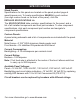
1.Disconnect all AC and DC power. To reduce the risk of electrical shock,
disconnect all AC and DC power during installation. This includes inverters,
generators, shore power attachments, and any other device capable of
supplyingACorDCpowertotheship’scircuits.
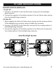
2. Select mounting location and cut opening. Select a convenient location
to mount the panel. When choosing a location, refer to the Cautions on
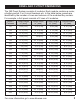
page 2. Also, choose a location that is protected from spray. Cut an opening
for the panel using the enclosed full size cutout template, or use the cutout
dimensions provided in the table on page 3.
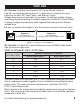
3. Verify circuit breaker ratings. Verifythateachbranchcircuitbreaker
installed is the correct rating for the circuit. The circuit breaker must have a
rating less than the allowable amperage of the wire, yet greater than the
circuit’scontinuouscurrent.Replacepre-installedcircuitbreakersifnecessary.
BlueSeaSystems’DCCircuitWizard, http://dc.circuitwizard.bluesea.com/
will guide you in suitable circuit protection selection.
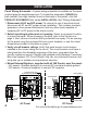
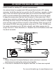
4. Mount External Busbars, supplied with all 360 Panels, near the panel:
• ACpanels—DualBusbusbar
(
s
)
to connect AC neutral and safety ground.
• DCpanels—Commonbusbar
(
s
)
to connect DC negative.
4
Formoreinformationgotowww.bluesea.com
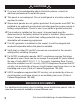
AC Panel DC Panel
+12V DC
+24V DC
NEG.
Connect to AC hot
Connect to AC neutral
AC
neutral
Safety ground
Connect to
AC loads
From
Loads
AC
+12V DC
+24V DC
NEG
Connect to
+ DC Loads
+ DC Positive
From
Loads
- DC
- DC Negative