
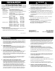
User guide
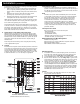

Wiring Diagram
DC Power Distribution Panel
(PN 8023 /PN 3023 shown for reference)
Installation (continued)
TO DC
NEGATIVE
FROM DC
POSITIVE
FUSE
1.0 TO 2.0A
DC BACKLIGHT
BOARD
Wire Sizing Chart
1. Calculate the maximum sustained amperage of the circuit. Measure
the length of the circuit from the power source to the load and back.
2. Does the circuit run in an engine space or non engine space.
3. Calculate Famps (Feet x amps). Multiply circuit length by max. current.
4. Base the wire on either the 3% or 10% voltage drop. In general, items
which affect the safe operation of the boat and its passengers (running
lights, bilge blowers, electronics) use 3%; all other loads use 10%.
5. Starting in the column which has the right voltage and voltage drop,
run down the list until arriving at a value which is greater than the
calculated Famps. Move left to the Ampacity column to verify that the
total amperage of the circuit does not exceed the maximum allowable
amperage of the wire size for that row. If it does, move down until the
wire ampacity exceeds the circuit amperage. Finally, move left to the
wire size column to select the wire size.
Example
a. A 12 volt system at 10% drop with a 40’ circuit x 45 amps = 1800
Famps. A wire size of 8 is required.
In Boatowner’s Illustrated Handbook of Wiring, Charlie Wing identifi es
three purposes of DC Grounding:
1. Holding conductive housings of low voltage (under 50 volts) DC
devices at ground potential by providing a low resistance return
path for currents accidentally coming into contact with the device
cases.
2. Providing a low resistance return path for electrical current,
preventing stray currents that may cause corrosion.
3. Grounding metal electrical cases to prevent emission from inside
or absorption from outside of radio frequency noise (RFI).
ABYC requires that grounding wires be sized no smaller than one wire
size under that required for current carrying conductors supplying the
device to which the grounding wire is connected.
A full treatment of this subject is not possible within the scope of these
instructions and there is controversy surrounding the general subject of
DC bonding, of which DC grounding is a component. It is suggested
that installers not familiar with this subject consult one of the reference
books listed elsewhere in these instructions.
8. Apply branch circuit labels and mount panel
Apply a label for each of the branch circuits from the 30 basic labels
provided. If the appropriate label is not included, the Extended Label
Set of 120 labels may be ordered from your marine supplier (PN 8039).
Individual labels are also available from Blue Sea Systems for specifi c
applications. Refer to the label order form for a complete listing of
individual labels.
Fasten the panel to the mounting surface using the panel mounting
screws supplied with the panel.
9. Testing
Reconnect the main positive cable to the battery terminals and turn the
main switch on to supply power to the panel. Turn on all branch circuits
and test the voltage at the panel. Compare this voltage to the battery
terminal voltage to determine that the voltage drop is within 3%. With
all branch circuits still on, test the voltage at one device on each circuit
to determine that there is a 3% or 10% drop as is appropriate.
Optional Branch LED’s
This Panel is supplied with LED’s pre-installed in all optional branch
positions. For future expansion of the panels remove the positive leg of
the LED from the negative busbar and connect it to the load side of the
corresponding branch circuit breaker.
Note
This Blue Sea Systems electrical distribution panel is furnished with
15 amp AC/DC circuit breakers. This rating was selected to minimize
the need for removing the panel’s circuit breakers and reinstalling
different size circuit breakers. As shown in the Wire Sizing Chart
included with these instructions, even 16 AWG wire, which is the
minimum wire size recommended by ABYC, has an allowable
amperage greater then 20 amps. Additionally, it would be rare to have
more than 15 amps of current fl owing in any one circuit. Therefore,
15 amp circuit breakers will satisfy the vast majority of marine circuit
protection situations.
The Purpose of a Panel
There are fi ve purposes of a marine electrical panel:
• Power distribution
• Circuit (wire) protection
• Circuit ON/OFF switching
• Metering of voltage and amperage (In panels with meters)
• Condition Indication (circuit energized)
Related Products from Blue Sea Systems
PanelBack Insulating Covers
High Amperage Fuses and Circuit Breakers for positive feed wires
High Amperage Battery Switches
Terminal Blocks and Common Bus Connectors