
User Manual

Installation (continued)
4. Install feed circuit wires
Install the feed wires from the shore power inlet or other AC source,
referring to the wire sizing chart to select the correct wire size. Connect
the black AC hot, white AC neutral and green AC safety ground as
shown in the illustration.
If the feed wires are from the shore power inlet or the electrical
attachment point of a permanently installed shore power cord and the
inlet or attachment point is more then 10 feet from this panel, an
additional fuses or circuit breakers must be installed within 10 feet of
the shore power inlet. The measurement is made along the
conductors.
5. Installation of Backlight System
The backlight board is a DC device. When installing it in an AC panel
both wire leads must be connected to an appropriate DC source and
ground.
Connect the yellow negative wire to a DC ground. Connect the red
positive wire to any DC positive supply, usually a switch that controls
the vessel’s other nighttime illumination.
6. Apply branch circuit labels and mount panel
Remove the blank labels installed in the panel before installing your
branch circuit labels. Apply a label for each of the branch circuits from
the 30 basic labels provided. If the appropriate label is not included,
individual labels are available from Blue Sea Systems for specifi c
applications. Refer to the label order form for a complete listing of
individual labels.
Fasten the panel to the mounting surface using the panel mounting
screws supplied with the panel.
7. Testing
@
Connect the vessel’s shore power and verify the Reverse Polarity
light is not illuminated. If the red Reverse Polarity light is on then
either the hot and ground or the hot and neutral wires have been
crossed. Starting at the panel, trace the connections back as far
as necessary to locate the error.
@ Using a multimeter where the power source is connected to the
panel verify:
PN 8074 / PN 3074 / PN 8409 / PN 3409 - 120 Volt AC
a. 120 volts between hot and neutral
(nominal, this may vary depending on source voltage)
b. 120 volts between hot and ground.
c. 0 volts between neutral and ground.
PN 8174 / PN 3174 / PN 8509 / PN 3509 - 230 Volt AC
a. 230 volts between hot and neutral
(nominal, this may vary depending on source voltage)
b. 230 volts between hot and ground.
c. 0 volts between neutral and ground.
@ Turn on each branch circuit to verify power to each circuit.
Optional Branch LED’s
This Panel is supplied with LED’s pre-installed in all optional branch
positions. For future expansion of the panel remove the hot leg of the
LED from the AC Neutral Bus and connect it to the Load side of the
branch circuit breaker.
Note
All Blue Sea Systems’ electrical distribution panels are furnished with
15 amp or 8 amp circuit breakers for branch circuits. 15 amp circuit
breakers are used in all 120 volt panels and 8 amp circuit breakers are
used in all 230 volt panels. These ratings were selected to minimize
the need for removing the panel’s circuit breakers and reinstalling
different size circuit breakers. It is very rare to have more than this
amount of current fl owing in any one circuit. Therefore, these circuit
breakers will satisfy the vast majority of marine circuit protection
situations.
The Purpose of a Panel
There are six purposes of a marine electrical panel:
• Power distribution
• Circuit (wire) protection
• Circuit ON/OFF switching
• Reverse Polarity Indication
• Metering of voltage and amperage (In panels with meters)
• Condition Indication (circuit energized)
Applicable Standards
• American Boat and Yacht council
Standards and recommended Practices for Small Crafts sections:
E-8, Alternating Current Electrical Systems on Boats.
• United States Coast Guard Code of Federal Regulations 33, Part
183, Subpart I, Electrical Systems on Boats.
Related Products from Blue Sea Systems
• PanelBack Insulating Covers
• High Amperage Fuses and Circuit Breakers for positive feed wires
• High Amperage Battery Switches
• Terminal Blocks and Common Bus Connectors
• AC Distribution Panels
• DC Distribution Panels
• AC and DC Digital and Analog Voltmeters and Ammeters
Useful Reference Books
Calder, Nigel, 1996: Boatowner’s Mechanical and Electrical Manual,
2nd edition, Blue Ridge Summit, PA: TAB Books, Inc.
Wing, Charlie, 1993: Boatowner’s Illustrated Handbook of Wiring,
Blue Ridge Summit, PA: TAB Books, Inc.
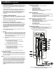
Wiring Diagram
AC Power Distribution Panel with Voltmeter and Ammeter
PN 8074 / PN 3074 shown for reference
FUSE
1.0 TO 2.0A
FROM DC
POSITIVE
TO DC
NEGATIVE
ADDITIONAL
BREAKER
REQUIRED
IF GREATER
THAN
10 FEET