E1100 ELECTRIC CONVECTION OVEN SERVICE MANUAL Revision 4/F3591 -1- © Moffat Ltd, August 2004
WARNING: ALL INSTALLATION AND SERVICE REPAIR WORK MUST BE CARRIED OUT BY QUALIFIED PERSONS ONLY.
CONTENTS This manual is designed to take a more in depth look at the E1100 electric convection oven for the purpose of making the unit more understandable to service people. There are settings explained in this manual that should never require to be adjusted, but for completeness and those special cases where these settings are required to change, this manual gives a full explanation as to how, and what effects will result. SECTION PAGE NO. 1. SPECIFICATIONS...............................................
Revision 4/F3591 -4- © Moffat Ltd, August 2004
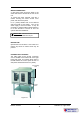
1. SPECIFICATIONS MODEL: E1100 1005 50 930 75 310 MWS E 3 E 1200 3 1390 190 WATER ENTRY MWS 660 ELECTRICAL ENTRY 205 FRONT MWS 3 SIDE E PLAN LEGEND - Electrical connection entry point - Water entry - ¾” BSP hose connection Dimensions shown in millimetres.
MODEL: E1100-2 1005 50 930 75 310 WATER ENTRY MWS E 3 E MWS E 3 E ELECTRICAL ENTRY 230 285 3 770 MWS 1690 3 730 MWS 205 FRONT MWS SIDE 3 E PLAN LEGEND - Electrical connection entry point - Water entry - ¾” BSP hose connection Dimensions shown in millimetres.
LOCATION The following minimum clearances for air openings, servicing, operation and installation are to be adhered to: Rear Left-hand side Right-hand side 100 mm 100 mm 300 mm OVEN INTERNAL DIMENSIONS Width Height Depth Oven Volume 730 mm 490 mm 600 mm 0.21 m³ OVEN RACK SIZE Width Depth: 710 mm 520 mm ELECTRICAL SUPPLY SPECIFICATION 400-415 V AC, 50 Hz, 10.4 kW, 3P+N+E 380V AC, 60Hz, 10.4kW, 3P+N+E WATER SUPPLY CONNECTION Max Pressure 550 kPa / 5.5 bar / 80 psi Min Pressure 100 kPa / 1.
2. INSTALLATION WARNING: THIS APPLIANCE MUST BE EARTHED / GROUNDED. WARNING: ALL INSTALLATION AND SERVICE REPAIR WORK MUST BE CARRIED OUT BY QUALIFIED PERSONS ONLY. Installations must be carried out by authorised persons only. Failure to install equipment to the relevant codes and manufacturers specifications in this section will void warranty. Rear Left-hand side Right-hand side NOTE: 300mm is required at the right hand side of the oven to allow access to the circuitry and gas connections.
WATER CONNECTION A cold water supply should be fitted to the water inlet which is located at the rear of the unit. To access the water solenoid, undo the 4 screws securing the water access cover panel, and remove the panel. Fit ½" (13mm) flexible hose to the solenoid and secure with a hose clamp. Turn on the water supply to check for leaks. It may be necessary to hold the water injection button in for a few seconds to remove air from the system after initial instalment.
3. OPERATION NOTE: A full user’s operation manual is supplied with the product and can be used for further referencing of installation, operation and service. 3.1 DESCRIPTION OF CONTROLS 1. POWER SWITCH Turn on to switch power on or off (indicator illuminates when power is on). 2. THERMOSTAT Temperature range 50 - 320°C. Indicator illuminates when elements are cycling ON to maintain set temperature. 1 3. BAKE TIMER 1 Hour bake timer. (Indicator illuminates when “time up” (0) reached, and buzzer sounds).
3.2 The temperature control of this oven is with a capillary type thermostat which can be set to a required cooking temperature. EXPLANATION OF CONTROL SYSTEM The thermostat switch has a separate switch body assembled onto the front from the shaft assembly and when the thermostat is set to a cooking temperature, the switch contacts turn on the oven fan. The switch is closed (fan on) whenever the thermostat is not in the Off (vertical) position.
When the 3 hour timer has run down and reached the Hold position the two switch contacts change over to their normally closed position which isolates power from the timer motor and the oven thermostat. It also switches power back to the oven hold thermostat. At this point the temperature control is now maintained by the hold thermostat as previously described. To cancel the hold circuit the Roast-and-Hold switch is turned Off.
4. MAINTENANCE WARNING: ALL INSTALLATION AND SERVICE REPAIR WORK MUST BE CARRIED OUT BY QUALIFIED PERSONS ONLY. 4.1 CLEANING 4.2 ROUTINE PROCEDURES WARNING: ALWAYS TURN THE POWER SUPPLY OFF BEFORE CLEANING. The following procedures should be carried out at least once a year. Door chain Check for wear. IMPORTANT: THIS UNIT IS NOT WATER PROOF. DO NOT USE A WATER JET SPRAY TO CLEAN INTERIOR OR EXTERIOR OF THIS UNIT. Door catch Ensure that catch is adjusted such that the door closes properly.
5. TROUBLE SHOOTING WARNING: ALL INSTALLATION AND SERVICE REPAIR WORK MUST BE CARRIED OUT BY QUALIFIED PERSONS ONLY. FAULT THE OVEN DOES NOT OPERATE / START POSSIBLE CAUSE REMEDY The mains isolating switch on Turn on. the wall, circuit breaker or fuses are “off” at the power board. The power switch on the oven is Turn on switch. Power indicator off. will illuminate. Incorrect electrical supply. (Refer fault diagnosis 6.1.1) Ensure electrical supply correct. Power switch on unit faulty.
FAULT OVEN LIGHT NOT ILLUMINATING POSSIBLE CAUSE REMEDY Blown bulb. Replace. (Refer service section 6.3.10) Light switch faulty. (Refer fault diagnosis 6.1.5) Replace. (Refer service section 6.3.2) Water not turned on. Turn water on at water supply. Oven water nozzle blocked. Remove, clean or replace. (Refer service section 6.3.14) Fault with water valve. (Refer fault diagnosis 6.1.6) Service or replace as required. (Refer service section 6.3.15, 6.3.16) Steam switch faulty.
FAULT SLOW RECOVERY POSSIBLE CAUSE REMEDY Oven in ‘Roast ‘n Hold’ mode. Switch off ‘Roast ‘n Hold’. Overloading of oven. Reduce oven loading. Fan not working. Check fan operation. One or more elements are faulty. Replace element. (Refer service section 6.3.13) Thermostat out of calibration. (Refer fault diagnosis 6.1.10) Correct calibration. (Refer service section 6.4.3) Contactor faulty (Refer fault diagnosis 6.1.10) Replace. (Refer service section 6.3.
6. SERVICE PROCEDURES WARNING: ENSURE POWER SUPPLY IS SWITCHED OFF BEFORE SERVICING. WARNING: ALL INSTALLATION AND SERVICE REPAIR WORK MUST BE CARRIED OUT BY QUALIFIED PERSONS ONLY. SECTION 6.1 FAULT DIAGNOSIS ..............................................................................................................19 6.1.1 6.1.2 6.1.3 6.1.4 6.1.5 6.1.6 6.1.7 6.1.8 6.1.9 6.1.10 6.1.11 6.1.12 6.1.13 6.2 Oven Does Not Operate / Start.......................................................................
6.3.19 6.3.20 6.3.21 6.3.22 6.4 Door Ball Catch....................................................................................................28 Door Linkage Chain Assembly ............................................................................28 Door Assembly.....................................................................................................29 Top Bearing Channel ...........................................................................................
6.1 FAULT DIAGNOSIS Fan motor faulty 6.1.1 OVEN DOES NOT OPERATE / START Check the supply voltage across motor terminals. If there is no voltage then check the electrical connections of wiring. Incorrect electrical supply If voltage is correct then check the oven fan for free rotation. Remove any obstruction. Check that the voltage across phase and neutral (L1 and L2) terminals of terminal block is the voltage as stated on the unit’s electrical rating plate.
6.1.5 OVEN LIGHTS NOT ILLUMINATING 6.1.7 CONTINUOUS WATER OUT OF OVEN WATER NOZZLE Light switch faulty Water solenoid electrical fault Check voltage to the left hand terminal of the switch. If there is no voltage, then check wiring. With control panel steam switch not depressed, check for power supply across solenoid coil. If there is power to the coil, then check wiring and steam switch (refer 6.1.7). With switch depressed, check voltage at right hand terminal.
thermostat on and off cycle. The thermostat should cycle on and off between 165°C and 195°C when set to the above temperature. If oven temperature is outside these ranges, then the thermostat requires recalibration. ‘Roast ‘n Hold’ switch faulty Check if the switch latches. If the switch does not latch then the switch is faulty—replace. With the switch latched, check voltage to terminal 2. If there is no voltage then check for fault in wiring.
6.2 ACCESS 6.2.4 RIGHT HAND SIDE PANEL 6.2.1 CONTROL PANEL 1) Remove the four screws along the top, four screws along the bottom, and the four screws from the rear of the right hand side panel. 1) Undo the screw on the left hand side of the control panel. Top screws (x4) One screw Rear screws (x4) Figure 6.2.1 2) The control panel can now hinge open along its right hand edge. Bottom screws (x4) Figure 6.2.4 2) Remove the panel. 6.2.
6.3 REPLACEMENT 6.2.6 CONTROL PANEL—REAR 6.3.1 POWER / ROAST SWITCHES 1) Open the control panel (refer 6.2.1). Power Indicator 2) Disconnect the wires from the faulty switch. Power Switch 3) Press in the locking tabs at top and bottom of the switch and from rear push switch through front of control panel. Locking tabs Thermostat Heating Indicator Time Up Indicator 60 Minute Timer Figure 6.3.1 4) Replace and reassemble in reverse order. Roast Switch 6.3.
3) Press in the locking tabs at top and bottom of the indicator and from rear push indicator through front of control panel. 3) Remove the two screws securing the thermostat phial mounting bracket to the RH wall of the oven. Feed the thermostat phial through into the control cavity. Locking tabs Thermostat bulb Figure 6.3.3 Figure 6.3.6 4) Replace and reassemble in reverse order. 5) Remove thermostat from oven. 6) Transfer wires to new thermostat. Reassemble with new thermostat in reverse order. 6.3.
5) Remove the two screws securing the thermostat phial mounting bracket to the RH wall of the oven. Feed the thermostat phial through into the control cavity. Locking Nut Thermostat bulb Figure 6.3.8 4) Transfer wires to the new timer and reassemble in reverse order. Figure 6.3.11 6.3.8 BUZZER 6) Remove thermostat from oven. 1) Remove R/H side panel (refer 6.2.4). 7) Transfer wires to new thermostat and reassemble with in reverse order. 2) Disconnect wires from buzzer (secured to insulation panel).
3) Pull the fan and motor assembly into the oven as pictured below, and disconnect the wiring. The fan motor unit can now be removed from the oven. 6.3.13 ELEMENTS 1) Remove the oven right hand side panel (refer 6.2.4). 2) Remove the wires from the element assembly. Figure 6.3.14 Figure 6.3.17 4) Slacken the two socket head grub screws spaced at 90o on the fan boss. 3) Remove the fan baffle (refer 6.2.2) 4) Remove the three screws securing the element mounting plate to the wall of the oven.
6.3.15 WATER SOLENOID VALVE 6.3.16 WATER SOLENOID CLEANING 1) Ensure water supply is turned off. 1) Remove water solenoid (refer 6.3.20). 2) Remove the water injection nozzle from inside the oven (refer 6.3.19). 2) Remove the two screws securing the bracket to the solenoid. 3) Remove the water solenoid access panel at the rear of the oven (4 screws). Two Screws Water solenoid access panel Figure 6.3.23 Figure 6.3.20 3) Remove the valve assembly.
3) Undo the two screws securing the microswitch to the microswitch bracket. Ball catch 4) Replace and reassemble in reverse order. 5) Adjust microswitch (refer 6.4.7) 6.3.18 DOOR GLASS Figure 6.4.27 1) Open the oven doors. 2) Remove the screws on the sides, top and bottom edges of the door with the broken glass. Locknut NOTE: If it is the left hand door, remove the extra screws and ball catches. Screws (x6) Figure 6.4.28 4) Replace and reassemble in reverse order.
3) Remove the door chain assembly and replace the broken component. 6) Undo the two screws securing the bottom pivot plate. 4) Reassemble in reverse order. 5) Adjust chain such that the oven doors close correctly (refer 6.4.1) 6.3.21 DOOR ASSEMBLY 1) Remove the bottom lintel (refer section 6.2.5). Two screws 2) Right hand door removal only: Remove the top lid. Remove the microswitch actuator pin from the door pin. Figure 6.3.
6.4 ADJUSTMENT / CALIBRATION 6.4.3 THERMOSTAT CALIBRATION IMPORTANT: IF THE OVEN TEMPERATURE NEEDS TO BE INCREASED, ENSURE THAT THE THERMOSTAT IS IN THE ‘OFF’ POSITION BEFORE CARRYING OUT ADJUSTMENT. IF OVEN TEMPERATURE NEEDS TO BE DECREASED, ENSURE THERMOSTAT IS IN THE ‘MAX’ TEMPERATURE POSITION BEFORE CARRYING OUT ANY ADJUSTMENT. 6.4.1 DOOR CHAIN 1) Remove the bottom lintel (refer 6.2.5). 2) Loosen the two locknuts on each of the turnbuckles.
6.4.5 60 MINUTE TIMER ZERO POSITION ADJUSTMENT Screws 1) Remove 60 minute timer knob by pulling it firmly away from control panel. Fan Switch 2) Open control panel (refer 6.2.1). Loosen two screws on control panel holding 60 minute timer. Figure 6.4.5 6) Adjust the calibration nut located at the base of the thermostat shaft. To increase oven temperature, calibration nut anticlockwise. turn To decrease oven temperature, calibration nut clockwise.
7.
-33- 2 5 3 HOLD 6 ROAST 1 4 36 TIME UP HEATING PRESET HOLD T/STAT 23 23 20 35 34 POWER 2 Revision 4/F3591 1 33 19 15 21 17 24 18 14 EARTH 25 6 29 27 16 4 41 7 4 8 7 15 16 10 LIGHT SW 24 17 14 3 6 3 18 1 MAINS SW. 1 28 4 5 1 21 27 WATER SW.
9. SPARE PARTS PART NO.
10. PARTS DIAGRAMS 10.1 MAIN ASSEMBLY 11 1 10 2 3 9 8 4 5 7 6 Pos Part No. Description 1 012229 Top cover 2 017959 LH side panel 3 ---------- Door assembly (Refer section 10.3) 4 011810 Bottom shroud 5 017410 Leg 6 010990 Foot - adjustable 7 013455 013708 Leg tray Leg tray bracket 8 ---------- Control panel assembly (refer section 10.
10.2 CONTROL PANEL ASSEMBLY Pos Part No.
10.
Pos Part No. Description 1 2 3 4 5 6 7 8 9 10 11 12 13 14 004070 004071 010627 010626 018081 018131 018138 002137 --------004287 ---------011005 018789 014138 017966 010145 014012 014011 DOOR INNER - L.H DOOR INNER - R.H DOOR OUTER - R.H DOOR OUTER - L.
11.
UNITED KINGDOM BLUESEAL LTD Units 6-7 Mount St Business Park Birmingham B7 5QU England Tel 0121-327 5575 Fax 0121-327 9711 UNITED STATES OF AMERICA MOFFAT INC.
APPENDIX A. DOUBLE STACKING INSTRUCTIONS Double Stacking Kit - Part number 016372 Figure A.1 1) Remove the leg tray and legs from both units. 4) Place the top unit onto the bottom unit and remove the screws along the back joining edge of both units. (See diagram). Screw on rear stacking plate. 2) Remove the leg securing frame from the top unit. 5) The top oven drain hole must be blocked up. Fit the bung provided. (To achieve a permanent seal we recommend also using some high temp silicone sealant).