INSTALLATION AND OPERATION MANUAL GAS RANGE STATIC OVEN G505 G506 G508 For use in GB & IE 230104-2
Contents Blue Seal Gas Static Oven Range G505 G506 G508 Gas Range Static Oven - 750mm wide. Gas Range Static Oven - 900mm wide. Gas Range Static Oven - 1200mm wide. Introduction..............................................................................................2 Specification..............................................................................................3 Model Numbers Covered in this Specification General Gas Supply Requirements Gas Connection Dimensions...........................
Introduction We are confident that you will be delighted with your BLUE SEAL GAS RANGE STATIC OVEN and it will become a most valued appliance in your commercial kitchen. To ensure you receive the utmost benefit from your new Blue Seal appliance, there are two important things you can do. Firstly: Please read the instruction book carefully and follow the directions given. The time taken will be well spent.
Specifications Model Numbers Covered in this Specification G505D[1] Gas Static Oven + 4 Open Burners. G505C[1] Gas Static Oven + 2 Open Burners + 300 mm Griddle. G506D[1] Gas Static Oven + 6 Open Burners. G506C[1] Gas Static Oven + 4 Open Burners + 300 mm Griddle. G506B[1] Gas Static Oven + 2 Open Burners + 600 mm Griddle. G506A Gas Static Oven + 900 mm Griddle. G508D[1] Gas Static Oven + 8 Open Burners + Storage Cabinet.
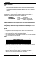
Specifications • UK Only Appliance Classification II 2H3P. Category: Flue Type: A1. Natural Gas (G20) Open Burner (each) Heat Input Nominal (nett) Reduced Gas Rate (nett) Propane (G31) Griddle (each 300mm section) Oven 6.5 kW 5.5 kW 8.0 kW 1.75 kW 1.85 kW 2.4 kW 3 3 3 Open Burner (each) Griddle (each 300mm section) Oven 6.5 kW 5.5 kW 8.0 kW 1.75 kW 1.95 kW 2.4 kW Nominal 0.69 m /hr 0.58 m /hr 0.85 m /hr 0.51 kg/hr 0.43 kg/hr 0.62 kg/hr Reduced 0.19 m3/hr 0.20 m3/hr 0.
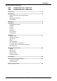
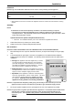
Dimensions G505 Cook Top Options G505C G505D 5
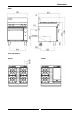
Dimensions G506 Cook Top Options G506D G506C G506B G506A 6
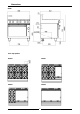
Dimensions G508 Cook Top Options G508D G508C G508B G508A 7
Installation Installation Requirements NOTE: • It is most important that this appliance is installed correctly and that operation is correct before use. Installation shall comply with local gas and health and safety requirements. • This appliance shall be installed with sufficient ventilation to prevent the occurrence of unacceptable concentrations of health harmful substances in the room, the appliance is installed in.
Installation Clearances NOTE: Only non-combustible materials can be used in close proximity to this appliance. Combustible Surface Non Combustible Surface Left/Right hand side 250 mm (*) 0 mm Rear 100 mm 0 mm * Side clearances can be 50 mm when the adjacent surface is at least 100 mm below the cooking surface. Assembly NOTE: • All Models are delivered completely assembled. No further assembly is required.
Installation The regulator connections are 3/4" BSP female. The connection to the appliance is 3/4" BSP male. (Refer to the “Specifications” section for the gas supply location dimensions). NOTE: A Manual Isolation Valve must be fitted to the individual appliance supply line. 4. 5. 6. Correctly locate the appliance into its final operating position and using a spirit level, adjust the legs so that the appliance is level and at the correct height. Connect the gas supply to the appliance.
Operation Operation Guide C AUTION : • This appliance is for professional use and is only to be used by qualified people. • Only authorised service persons should be used to carry out installation, servicing or gas conversion operations. • Components having adjustments protected (e.g. paint sealed) by the manufacturer should not be adjusted by the user/operator. 1. 2. Blue Seal appliances have been designed to provide simplicity of operation and 100% safety protection.
Operation Open Burners NOTE: Only cooking pans from size Ø 150 mm to Ø 420 mm are suitable fo use on these open burners. Flame Failure Option (F-Models) Lighting the Open Burners Flame Failure Protection is incorporated for each burner by way of a thermo-electric system which will shut off the gas supply to that burner in the event that the burner goes out, so that un-burnt gas is not expelled. a.
Operation Griddle CAUTION: The griddle plate temperature reaches over 300°C in hottest points during normal operation at 'Full Flame' setting. Lighting the Griddle a. Depress the gas control knob and rotate anti-clockwise to the ‘PILOT’ position. b. With the gas control knob depressed, press the piezo ignition button to ignite the pilot burner. Repeat Items 1 to 2 until the pilot is lit. c. Release the gas control knob approximately 10-20 seconds after lighting the pilot. d.
Operation Oven Pilot Ignition This oven is fitted with a pilot as a standard option and flame failure protection, which is incorporated by way of a thermo-electric system for the main burner. Flame failure protection will shut off the gas supply to the burner in the event that the pilot burner goes out, so that un-burnt gas is not expelled. This is an . important safety feature which is slowly becoming law throughout the world ! IMPORTANT 1. 2. 3. 4.
Cleaning and Maintenance CAUTION: Always turn off the gas supply before cleaning. This appliance is not water proof. Do not use water jet spray to clean interior or exterior of this appliance. General Clean the range regularly. A clean range looks better, will last longer and will perform better. Carbonised grease on the surface or between the trivets, griddle plates will hinder the transfer of heat from the cooking surface to the food. This will result in loss of cooking efficiency.
Cleaning and Maintenance Daily Cleaning 1. 2. 3. 4. The grease / spill tray(s) should be checked and emptied frequently to prevent overflow and spillage. Remove the grease / spill tray(s) while still warm so that the grease is in a liquid state. Empty any grease from the trays and wash thoroughly in the same manner as any cooking utensil.
Cleaning and Maintenance Trivets and Burners a. Remove the trivets from the top of the appliance, taking note that the trivets are manufactured with a lip on one edge, the lip must always be fitted to the outer edge (front and back) of the cook top. (Refer to Fig 10 overleaf). b.
Cleaning and Maintenance Notice Lip on Trivet Edge NOTE: It is imperative that the trivet supports are correctly re-fitted to the appliance to ensure that the trivets locate correctly and sit flush and level. NOTE that the trivet support front end, side rail profiles are different at either side (See Fig 6) and only one of the side rails seat into the cut-out in the range top, where as the rear end of the trivet support side rail profiles are the same and have 2 cut-outs to locate into. b.
Fault Finding This section provides an easy reference guide to the more common problems that may occur during the operation of your appliance. The fault finding guide in this section is intended to help you correct, or at least accurately diagnose problems with your equipment. Although this section covers the most common problems reported, you may encounter a problem not covered in this section.
Gas Conversion and Specifications Conversion Procedure CAUTION: Ensure that the appliance is isolated from the gas supply before commencing servicing. Burner Cap NOTE: • These conversions should only be carried out by qualified persons. All connections must be checked for leaks before re-commissioning the appliance. • For all relevant gas specifications refer to the table at the end of this section. Open Burners ('F' - Flame Failure Option) 1. 2. 3. 4. 5. 6. 7. 8. 9. 10. 11.
Gas Conversion and Specifications 12. 13. Notice Lip on Trivet Edge Refit all the trivet supports to the top of the appliance. Note the orientation of the trivet support when re-fitting as the front end side rail profiles are different from the rear end side rail profiles. (See Fig 14). Refit the trivets to the top of the appliance taking note that the trivets are manufactured with a lip on one edge, the lip must always be fitted to the outer edge (front and back) of the cook top. (See Fig 18).
Gas Conversion and Specifications Pilot Injectors a. Unscrew and remove the Pilot Injector Plug from the fitting at the end of the pilot injector tube using a 11 mm A/F spanner. (Refer to Fig 23). b. Using a flat bladed screwdriver, unscrew and remove the pilot injector from the pilot injector housing. NOTE Pilot Injector Housing Take care not to lose the spring fitted in front of the injector. c. Remove existing pilot injector and replace with the correct size pilot injector for the gas type being used.
Gas Conversion and Specifications Griddle Pilot Burner a. With the gas supply turned off at the main supply, remove the griddle plate section by lifting it straight off the cook top. b. Remove the gas control heat shield from around the griddle burner, this is just a push in fit. c. Disconnect the thermocouple and the piezo igniter from the mounting bracket. (For access purposes). (See Fig 27). d. Disconnect the pilot supply tube from the pilot burner with a 13 mm (½") spanner. (See Fig 27). e.
Gas Conversion and Specifications Shown with door removed for ease of viewing Oven Injector: a. With the gas supply turned off at the main supply, unscrew and remove the 6 screws securing the lower lintel to the front of the oven. (See Fig 30). b. Open the oven door and remove the cast oven sole plate from inside the oven. c. Remove the 2 screws securing the oven burner in the oven and remove the main burner from the oven. d.
Gas Conversion and Specifications Gas Regulator NOTE: The regulator supplied is convertible between Natural Gas and LPG, but it’s outlet pressure is fixed ex-factory and is NOT to be adjusted. NOTE, Pin rotated for Natural Gas NOTE, Pin rotated for LPG Fig 34 1. 2. 3. 4. Ensure that the gas supply is turned ‘OFF’ at the mains supply. Unscrew the hexagonal cap (23mm A/F) from the regulator.
Gas Conversion and Specifications Commissioning Before leaving the converted installation; 1. Check all gas connections for leakages using soapy water or other gas detecting equipment. WARNING: DO NOT USE A NAKED FLAME 2. TO CHECK FOR GAS LEAKAGES. Check the following functions in accordance with the operating instructions specified in the ‘Operation’ section of this manual. • Light the Pilot Burners. • Light the Main Burners. • Check the Low Fire Burner operation.
Gas Conversion and Specifications - UK Only Appliance Classification Category: Flue Type: II 2H3P. A1. Natural. Gas (G20) Open Burner Griddle Oven Main Burner Injectors Propane (G31) Ø 2.30 mm Ø 1.40 mm 0.30 0.20 Main Burner Ø 2.10 mm Ø 1.30 mm Pilot Burner 0.35 0.23 Main Burner Ø 2.60 mm Ø 1.60 mm Pilot Burner 0.35 0.23 Ø 1.5 mm Ø 0.95 mm 20 mbar 37 mbar 9.
Replacement Parts List Replacement Parts List IMPORTANT: Only genuine authorized replacement parts should be used for the servicing and repair of this appliance. The instructions supplied with the parts should be followed when replacing components. For further information and servicing instructions, contact your nearest authorized service branch (contact details are as shown on the reverse of the front cover of this manual).
Replacement Parts List Oven 228767 018691K 020253 018743 032160 019217 228703 022407 227508 Piezo 019407 227381 Oven Oven Burner. Oven Pilot. Oven Thermocouple. Thermocouple Spacer. Oven Burner Injector (LPG) Pilot Injector (LPG) Thermostat / Gas Control Kit. Low Fire Screw (LPG) Ignitor. H.T Lead. Knob 100-290°C. 1.60 mm. 0.23 mm. 0.95 mm. General 227014 228884 228883 228882 227850 229674 Spill Spill Spill Rear Pot Stand / Trivet. Tray (G505 Series). Tray (G506 Series). Tray (G508 Series).