Gas Cooktops G51 Service Manual Blue Seal Evolution series G51 Gas Cooktops Revision 1/ © Moffat Ltd, January 2007
WARNING: ALL INSTALLATION AND SERVICE REPAIR WORK MUST BE CARRIED OUT BY QUALIFIED PERSONS ONLY. IMPORTANT: MAKING ALTERATIONS MAY VOID WARRANTIES AND APPROVALS.
Contents This manual is designed to take a more in depth look at the Blue Seal Gas Cooktops for the purpose of making the units more understandable to service people. There are settings explained in this manual that should never require to be adjusted, but for completeness and those special cases where these settings are required to change, this manual gives a full explanation as to how, and what effects will result. Section Page Number 1. Specifications ..................................................
Blue Seal Evolution series G51 Gas Cooktops Revision 1/ © Moffat Ltd, January 2007
Specifications 1 Model Numbers Covered in this Specification G512D-[1]-[2] G512C -[2] 2 Open Burners. 300 mm Griddle. G514D-[1]-[2] G514C-[1]-[2] G514B -[2] 4 Open Burners. 2 Open Burners + 300 mm Griddle. 600 mm Griddle. G516D-[1]-[2] G516C-[1]-[2] G516B-[1]-[2] G516A -[2] 6 Open Burners. 4 Open Burners + 300 mm Griddle. 2 Open Burners + 600 mm Griddle. 900 mm Griddle. G518D-[1]-[2] G518C-[1]-[2] G518B-[1]-[2] G518A-[1]-[2] 8 6 4 2 Open Open Open Open Burners. Burners + 300 mm Griddle.
1 Specifications Gas Supply Requirements - UK Models Only Appliance Classification II2H3P. A1. Category: Flue Type: Natural Gas (G20) Open Burner Griddle Heat Input (nett) Gas Rate (nett) Nominal Reduced Nominal Reduced Supply Pressure Burner Operating Pressure (each) (each 300mm section) 6.5 kW 1.75 kW 0.69 m3/hr 0.19 m3/hr 5.5 kW 1.85 kW 0.58 m3/hr 0.20 m3/hr Propane (G31) Open Burner Griddle (each) (each 300mm section) 6.5 kW 1.75 kW 0.51 kg/hr 0.14 kg/hr 5.5 kW 1.95 kW 0.43 kg/hr 0.
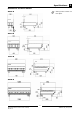
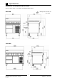
Specifications 1 Dimensions for Bench Models G512-B R = Rating Plate Location for this option.
1 Specifications Dimensions for Cabinet Base Models G512 models - not available in Cabinet Base option. G514-CB R = Rating Plate Location for this option.
Specifications 1 Dimensions for Leg Stand Models G512 models - not available in Leg Stand Base option. G514-LS R = Rating Plate Location for this option.
1 Specifications Dimensions for Refrigerated Base Models G512 and G514 models - not available in Refrigerated Base option. G516-RB R = Rating Plate Location for this option.
Specifications 1 Cooktop Options G518-D G516-D G514-D G512-D G518-C G516-C G514-C G512-C G518-B G516-B G514-B G518-A G516-A NOTE: • G512 models are only available in Bench Model (-B) option. • G514 models are available in Bench Model (-B), Cabinet Base (-CB), or Leg Stand (-LS) model options. • G516 and G518 models are available in Bench Model (-B), Cabinet Base (-CB), Leg Stand (-LS), or Refrigeration Base (-RB) model options.
2 Installation Installation Requirements NOTE: • It is most important that this Cooktop is installed correctly and that operation is correct before use. Installation shall comply with local gas, health and safety requirements. • This appliance shall be installed with sufficient ventilation to prevent the occurrence of unacceptable concentrations of health harmful substances in the room, the appliance is installed in.
Installation 2 Location 1. 2. 3. 4. 5. Installation must allow for a sufficient flow of fresh air for the combustion air supply. Installation must include adequate ventilation means, to prevent dangerous build up of combustion products. Never directly connect a ventilation system to the appliance flue outlet. Position the appliance in its approximate working position. All air for burner combustion is supplied from underneath the appliance.
2 Installation Gas Connection NOTE: ALL GAS FITTING MUST ONLY BE CARRIED OUT BY A QUALIFIED PERSON. 1. 2. Blue Seal Cooktops do not require electrical connection, as they function totally on the gas supply. It is essential that the gas supply is correct for the Cooktop to be installed and that adequate supply pressure and volume are available. The following checks should therefore be made before installation:a.
Installation 2 Commissioning Before leaving the new installation; Check the following functions in accordance with the operating instructions specified in the ‘Operation’ section of this manual. • Lighting the Griddle. • Light the Open Burners. (F - Option). • Light the Open Burners. (PF - Option). • Check the Low Fire burner operation. Ensure that the operator has been instructed in the areas of correct lighting, operation, and shutdown procedure for the appliance.
3 Operation 3.1 Note: Description of controls A full user’s operation manual is supplied with the product and can be used for further referencing of installation, operation and service. C AUTIO N • This appliance is for professional use and is only to be used by qualified persons. • Only authorised service persons are allowed to carry out installation, servicing or gas conversion operations. • Components having adjustments protected (e.g.
Operation 3.2 3 Explanation of Control System Safety System Electromagnetic Flame Failure Gas Valve The purpose of the safety system is to shut off the flow of gas if the pilot flame goes out. It is comprised of the flame itself, the thermocouple, and the flame failure gas valve. The purpose of the safety valve is to shut off the flow of gas if the pilot flame goes out. Inside the body of the gas valve is an electromagnet connected to a spring loaded plunger.
4 Cleaning / Maintenance CAUTION: Always turn off the gas supply before cleaning. This unit is not water proof. Do not use water jet spray to clean interior or exterior of this appliance. 4.1 Cleaning Procedure Routine Maintenance After Each Use To achieve the best results cleaning must be regular and thorough and all controls and mechanical parts checked and adjusted periodically by a competent serviceman. If any small faults occur, have them attended to promptly.
Cleaning / Maintenance Weekly Cleaning 4 use a griddle stone or a scotch bright pad on the griddle surface. Note: b) A scraper tool can be used for the removal of stubborn carbon and deposits. • If the cooktop usage is very high, we recommend that the weekly cleaning procedure is carried out on a more frequent basis. c) Occasionally bleach the griddle plate with vinegar when the plate is cold. • Ensure that protective gloves are worn during the cleaning process.
4 Cleaning / Maintenance solution and a soft scrubbing brush. Note that the gas control knobs are a push fit onto the gas control valve spindles and can be removed to allow cleaning of the front control panel. c) Refit the top part of the burner (cast brass) onto the lower portion already fitted to the manifold. This is a loose fit into the lower part of the burner.
Cleaning / Maintenance 4.2 4 Routine Maintenance G51 BLUE SEAL COOKTOP - MAINTENANCE SCHEDULE Business Name and Address: Date: Service Report No. Phone: Fax: Serial No: Clients Order No. Serviceman: Remarks Model: G51 1 Inspect exterior condition of unit. 2 Check working gas pressure correct to rating plate. 3 Regrease gas cocks (Cooktop / Griddle if fitted). 4 Inspect thermocouples (cooktop, griddle-if fitted).
5 Trouble-shooting WARNING: 5.1 ALL INSTALLATION AND SERVICE REPAIR WORK MUST BE CARRIED OUT BY QUALIFIED PERSONS ONLY. Trouble Shooting Chart Open burners Fault Pilot won’t light (PF fitted burners only) Main burners will not light. Main burners go out when control knob released. Possible cause Remedy Gas control knob not being held in. Hold in button while lighting pilot. No gas supply. Ensure gas is connected and on (bottles not empty). Gas pressure too low. Check gas supply pressure.
Trouble-shooting 5 Open burners Fault Main burner flame incorrect colour (yellow / wavy) Pilot flame small / lazy / yellow. (PF fitted burners only) Pilot goes out when knob released. (PF fitted burners only) Possible cause Remedy Incorrect gas pressure. Check supply pressure. Incorrect injector size. Check injector correct size. Obstruction in burner. Inspect burner for obstruction. Gas pressure too low. Check gas supply pressure.
5 Trouble-shooting Griddle burners Fault Pilot won’t light Piezo ignitor not sparking. Pilot flame small / lazy / yellow. Pilot goes out when knob released. Possible cause Remedy Gas control knob not being held in. Hold in button while lighting pilot. No gas supply. Ensure gas is connected and on (bottles not empty). Gas pressure too low. Check gas supply pressure. (Refer specifications section) Blocked pilot injector. Clean or replace pilot injector. (Refer service section 6.2.
Trouble-shooting Fault Main burner flame incorrect colour (yellow / wavy). Pilot goes out when main burner comes on. Possible cause 5 Remedy Aeration setting incorrect. Adjust aeration. (Refer service section 6.4.4) Incorrect gas pressure. Check supply pressure. Incorrect injector size. Check injector correct size. Obstruction in burner. Inspect burner for obstruction. Incorrect gas pressure. Check supply / adjust pressure. (Refer specifications section) Faulty gas control.
5 Trouble-shooting 5.2.2 5.2 Fault diagnosis 5.2.1 Pilot goes out when pilot knob is released Piezo ignitor not sparking Short in high tension lead If repeated sparking of the piezo shows intermittent sparking at the electrode, then the lead should be traced to find area of short. This can normally be visually seen as the spark arcs. If the lead is shorting the best solution is to replace it, as the electrical insulation strength of the lead may have deteriorated.
Service Procedures Section 6 Page no. 6.1 Access .................................................................................................... 24 6.1.1 Hob Control Panel .................................................................................................... 24 6.2 Replacement ........................................................................................... 24 6.2.1 6.2.2 6.2.3 6.2.4 6.2.5 6.2.6 6.2.7 6.2.8 6.2.9 6.2.10 6.2.11 6.2.12 6.2.13 6.2.14 6.2.
6 Service Procedures 6.1 Access 6.2 6.1.1 Hob control panel 6.2.1 Open Burner Venturi Replacement – Cook Top 1) Remove both pot stand castings (front and rear ). 1) Remove all gas control knobs by pulling away from the control panel. 2) Remove drip tray. 3) Loosen the two screws control panel to the hob. securing the 3) Remove the control panel. Front and rear pot stands 4) Griddle models will require H.T lead to be disconnected from rear of piezo ignitor on control panel. Figure 6.2.
Service Procedures 6 6.2.2 Open burner injector 4) Undo two cap screws securing thermocouple bracket and (Pilot burner if applicable) and remove bracket. 1) Remove both pot stands (front and rear). Front and rear pot stands Bracket cap screws Figure 6.2.1d Figure 6.2.2a 2) Remove burner caps and bowls (front and rear). Securing nut Open burner injector Caps and bowls Figure 6.2.1e Burner venture securing screws Figure 6.2.2b 3) Remove two cap screws securing burner guard and remove burner guard.
6 Service Procedures 4) Undo injector and replace. 5) Undo thermocouple from bottom of burner bracket and rear of gas control, remove thermocouple and replace. Open burner injector Thermocouple bracket securing nut Figure 6.2.2d Figure 6.2.3c 5) Reassemble in reverse order. Ensure that burner bowls are seated correctly on cap screw heads. 6.2.3 Thermocouple to gas control connection Open burner thermocouple 1) Remove front control panel (refer 6.1.1). 2) Remove both pot stands (front and rear).
Service Procedures 6.2.4 Open burner gas control 6 6.2.5 Open burner pilot (PF models) 1) Remove control panel (refer 6.1.1 access). 1) Remove both pot stands (front and rear). 2) Undo open burner gas supply line from gas control. 2) Remove burner caps and bowls (front and rear). 3) Remove two screws securing each pilot burner shield. Gas control supply connection 2 Pilot Burner Shield Screws Open burner gas supply line Figure 6.2.4a 3) Undo thermocouple from rear of gas control.
6 Service Procedures 6.2.7 Gas control magnet 1) Remove the burner (refer 6.3.1 / 6.3.8) and the heat shield. 2) Remove the thermocouple from the rear of the gas control (refer figure 6.3.22). Spring Injector 3) Remove the rear nut from gas control. Cap 4) Extract gas magnet. 5) Replace and reassemble in reverse order. Figure 6.2.5c 6.2.6 Griddle burner gas control 1) Remove control panel. 2) Unscrew main burner supply, pilot burner supply and thermocouple from gas control.
Service Procedures 6.2.9 Griddle burner injector 6 5) Remove pilot burner from bracket (two screws). 1) Remove griddle plate. 6) Replace and reassemble in reverse order. 2) Remove griddle burner (refer 6.2.10). Ensure that the thermocouple is NOTE: positioned correctly in the holder before tightening up. 3) Lift out stainless steel reflector plate. Burner 6.2.11 Griddle pilot burner thermocouple Reflector plate 1) Remove griddle plate and reflector plate. 2) Remove griddle burner (refer 6.2.10).
6 Service Procedures 6.2.12 Griddle pilot burner injector 6.2.14 Griddle burner H.T Lead 1) Remove griddle plate and reflector plate. 1) Remove control panel (refer 6.1.1). 2) Remove griddle burner (refer 6.2.10). 2) Remove H.T. lead from piezo ignitor and pilot electrode. 3) Unscrew the pilot supply tube from the pilot burner assembly. Pilot supply Figure 6.2.14 3) Replace lead and reassemble in reverse order. Figure 6.2.12 4) Extract injector from pilot burner.
Service Procedures 6.3 6.3.2 Adjustment/ calibration 6 Cooktop low fire adjustment 1) Light burner and turn gas tap to low position. 6.3.1 2) Remove gas control knob. Cooktop gas tap re-greasing 3) Turn low fire adjustment screw, located below and to the right of the gas control shaft, until the desired low flame is achieved. 1) Remove control panel (refer 6.1.1). 2) Remove 2 screws holding shaft plate to gas control body and remove control shaft and plate.
7 Accessories 32 Blue Seal Evolution series G51 Gas Cooktops Revision 1/ © Moffat Ltd, January 2007
Exploded Parts Diagrams 8.1 G51 Gas Cooktops 8.1.
8 Exploded Parts Diagrams G51 Main Assembly ITEM PART NO 1 228670 227794 227836 228420 2 228809 228672 228669 228662 3 PG312 PG612 PG912 4 228288 5 229360 227538 227537 227236 6 230286 230273 230277 7 227014 8 227960 9 227690 10 227330 11 228692 227277 227278 228155 DESCRIPTION BACK PANEL 300MM BACK PANEL 600MM BACK PANEL 900MM BACK PANEL 1200MM SPLASHBACK BSEAL 300MM SPLASHBACK BSEAL 600MM SPLASHBACK BSEAL 900MM SPLASHBACK BSEAL 1200MM GRIDDLE PLATE GAS 300MM WA GRIDDLE PLATE GAS 600MM WA GRIDDLE PLATE
Exploded Parts Diagrams 8.1.2 8 G51 Open Burners (F Models) ITEM PART NO 12 227017 13 227018 14 227455 15 227457 16 017802 17 017804 18 017803 19 227405 20 228167 21 227379 22 227019 23 030245 030230 030150 030140 24 227456 25 227132 26 228166 27 227627 DESCRIPTION BURNER CAP BURNER BODY BURNER COVER PANEL STD REAR BURNER SUPPLY PIPE INLET SPIGOT 10MM NUT - 10mm STEEL OLIVE 10MM BRASS GAS VALVE 20S-B CW 3-8 ELBOW THERMOCOUPLE 320mm KNOB BSEAL 8MM GAS STD / F BURNER VENTURI INJECTOR 2.
8 Exploded Parts Diagrams 8.1.
Exploded Parts Diagrams 8.1.4 8 G51 Griddle Burners 61 ITEM 48 49 50 50 51 52 53 54 55 56 57 58 59 60 61 PART NO 230213 014105 032210 032130 228047 228223 228010 227508 011148 227594 022686 019428 227178 227765 019215K 026488 019217 018744 DESCRIPTION GRIDDLE REFLECTOR ASSY GRIDDLE BURNER INJECTOR 2.1mm (NAT GAS) INJECTOR 1.
8 Exploded Parts Diagrams 8.2 G51 Base Options 8.2.1 Bench Mount Base ITEM PART NO 1 230354 2 228663 227123 227120 227125 3 227855 4 227852 5 230355 6 228670 228313 227121 228314 DESCRIPTION SIDE COVER RH TOP TRIM 300MM WIDE TOP TRIM 600MM WIDE TOP TRIM 900MM WIDE TOP TRIM 1200MM WIDE LEG 80MM X Ø63.
Exploded Parts Diagrams 8.2.2 ITEM 1 2 3 4 5 6 7 8 9 10 11 12 8 Cabinet Base PART NO 227048 228321 227075 227901 227409 227790 227789 227791 227788 227787 227786 227850 227852 227049 229674 229671 227040 227104 227117 228935 DESCRIPTION SIDE PANEL RH SIDE RACK WA SILL 600MM WA SILL 900MM WA SILL 1200MM WA FILLER 600MM FILLER 900MM FILLER1200MM SIDE SUPPORT 600MM CENTRE SUPPORT 900MM CENTER SUPPORT 1200MM LEG 150MM X Ø63.
8 Exploded Parts Diagrams 8.2.3 Leg Base ITEM PART NO 1 230354 2 227123 227120 227125 3 227853 4 227408 227407 227409 5 227075 227901 227902 6 227851 7 229674 8 748010 9 229673 10 230355 11 228313 228312 228314 DESCRIPTION SIDE COVER RH TOP TRIM 600MM TOP TRIM 900MM TOP TRIM 1200MM LEG EXTENSION 530 X Ø63.5 BASE TRAY 600MM BASE TRAY 900MM BASE TRAY 1200MM SILL 600MM WA SILL 900MM WA SILL 1200MM WA LEG 150MM X Ø63.
Service Contacts 9 Australia VICTORIA - MOFFAT PTY HEAD OFFICE AND MAIN WAREHOUSE 740 Springvale Road Mulgrave VIC 3170 Spare Parts Department Tel (03) 9518 3888 Fax (03) 9518 3838 Free Call 1800 337 963 Fax (03) 9518 3895 NEW SOUTH WALES - MOFFAT PTY Unit 3/142 James Ruse Drive Rosehill NSW 2142 Spare Parts Tel (02) 8833 4111 Free Call 1800 337 963 Fax (03) 9518 3895 QUEENSLAND - MOFFAT PTY 30 Prosperity Place Geebung QLD 4034 Spare Parts Tel (07) 3630 8600 Free Call 1800 337 963 Fax (03) 9518 3895
9 Service Contacts United Kingdom BLUESEAL LTD 67 Gravelly Industrial Park Erdington Birmingham B24 8TQ England Tel 0121 327 5575 Fax 0121 327 9711 United States of America MOFFAT INC.
Appendix A: Gas Type Conversion A Gas type conversion procedure NOTE: • These conversions should only be carried out by qualified persons. All connections must be checked for leaks before re-commissioning the appliance. • For all relevant gas specifications refer to the table at the end of this section. Open Burners ('F' - Flame Failure Option) 1. 2. 3. 4. 5. 6. 7. Turn ‘OFF’ the gas supply at the main supply.
A 12. 13. Appendix A: Gas Type Conversion Refit all the trivet supports to the top of the appliance. Note the orientation of the trivet support when re-fitting as the front end side rail profiles are different from the rear end side rail profiles. (See Fig 13). Refit the trivets to the top of the appliance taking note that the trivets are manufactured with a lip on one edge, the lip must always be fitted to the outer edge (front and back) of the cook top. (See Fig 12). Low Fire Adjustment a.
Appendix A: Gas Type Conversion Pilot Injectors a. Unscrew and remove the Pilot Injector Plug from the fitting at the end of the pilot injector tube using a 11 mm A/F spanner. (Refer to Fig 20). b. Using a flat bladed screwdriver, unscrew and remove the pilot injector from the pilot injector housing. A Pilot Injector Housing Pilot Injector Plug Fig 20 NOTE Take care not to lose the spring fitted in front of the injector. c.
A Appendix A: Gas Type Conversion Griddle Pilot Burner a. With the gas supply turned off at the main supply, remove the griddle plate section by lifting it straight off the cook top. b. Remove the gas control heat shield from around the griddle burner, this is just a push in fit. c. Disconnect the piezo igniter from the mounting bracket. (For access purposes). d. Disconnect the pilot supply tube from the pilot burner with a 13mm (½") spanner. e.
Appendix A: Gas Type Conversion A Gas Regulator NOTE, Pin rotated for Natural Gas NOTE, Pin rotated for LPG Fig 27 NOTE: The regulator supplied is convertible between Natural Gas and LP Gas, but it’s outlet pressure is fixed ex-factory and is NOT to be adjusted. 1. 2. 3. 4. Ensure that the gas supply is turned off. Unscrew the hexagonal cap (23mm A/F) from the regulator. Un-clip the plastic pin from the cap, reverse the pin and re-fit it back to the cap the correct way for the gas type to be used.
A Appendix A: Gas Type Conversion Commissioning Before leaving the converted installation; 1. Check all gas connections for leakages using soapy water or other gas detecting equipment. WARNING DO NOT USE A NAKED FLAME 2. TO CHECK FOR GAS LEAKAGES. Check the following functions in accordance with the operating instructions specified in the “Operation” section of this manual. • Light the Pilot Burners. • Light the Main Burners. • Check the Low Fire burner operation.
Appendix A: Gas Type Conversion A - UK Only Appliance Classification Category: Flue Type: Open Burner Griddle II2H3P. A1. Natural. Gas (G20) Propane (G31) Ø 2.30 mm Ø 1.40 mm 0.30 0.20 Main Burner Ø 2.10 mm Ø 1.30 mm Pilot Burner 0.35 0.23 20 mbar 37 mbar 9.