
Service manual

A
Appendix A: Gas Type Conversion
45
© Moffat Ltd, January 2007
Revision 1/
Blue Seal Evolution series G51 Gas Cooktops
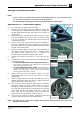
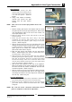
Pilot Injectors
a. Unscrew and remove the Pilot
Injector Plug from the fitting at the
end of the pilot injector tube using
a 11 mm A/F spanner. (Refer to
Fig 20).
b. Using a flat bladed screwdriver,
unscrew and remove the pilot
injector from the pilot injector
housing.
NOTE Take care not to lose the spring fitted in front of the
injector.
c. Remove existing pilot injector and replace with the correct
size pilot injector for the gas type being used. Refer to the
‘Gas Specifications’ table at the end of this section, for
correct pilot injector sizes.
d. Refit the spring and the correct pilot injector to the pilot
injector housing.
e. Screw the pilot injector fully home using a flat blade
screwdriver and refit the pilot injector plug to the pilot
injector housing and tighten in place using a 11 mm A/F
spanner. (Refer to Fig 20).
f. Refit the splash guard over the gas cocks taking care not to
damage the thermocouples and pilot burner tubes. Secure
in position with the 2 allan headed screws. (Note that the
splash guard for 'FP' models has a different cut-outs for
pilot burner tubes. Refer to Fig 22).
g. Refit the pilot burner tube shields over the pilot burner
tubes / thermocouples and secure in place with the 2
securing screws. (Refer to Fig 18).
h. Refit the burner caps and burner bowls onto the manifolds
protruding through the splash guards. Take note that the
base part of the burner bowl has 2 locating holes drilled
into the base flange, these are to locate the burner bowl
onto the allen headed screws that secure the splash guard
to the gas manifold. (Refer to Fig 15).
i. Refit all the trivet supports to the top of the appliance.
Note the orientation of the trivet support when re-fitting as
the front end side rail profiles are different from the rear
end side rail profiles. (Refer to Fig 13).
j. Refit the trivets to the top of the appliance taking note that
the trivets are manufactured with a lip on one edge, the lip
must always be fitted to the outer edge (front and back) of
the cook top. (Refer to Fig 12).
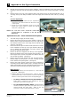
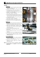
Low Fire Adjustment
a. To adjust the open burner low fire adjustment, remove the
gas control knobs from the front of the control panel.
b. Adjust the low fire adjustment screw on the open burner
gas control valves to obtain the desired flame size. (Refer
to Fig 23).
NOTE: The “Low Fire Screw” should be sealed with coloured
paint on completion of the low fire adjustment.
Pilot Injector
Plug
Pilot Injector
Housing
Low Fire Adjustment Screw
Fig 23
Fig 20
Fig 21
Cut-Out for Pilot
Burner &
Thermocouple
Fig 22
Shown without Pilot
Burner Shield fitted.
Pilot Burner
Thermocouple