
Specifications


23
11. Refit all the trivet supports to the top of the appliance. Note
the orientation of the trivet support when
re-fitting as the front end side rail profiles are different from
the rear end side rail profiles. (Refer to Fig 12 on previous
page).
12. Refit the trivets to the top of the appliance taking note that
the trivets are manufactured with a lip on one edge, the lip
must always be fitted to the outer edge (front and back) of
the Cooktop. (Refer to Fig 11 on previous page).
13. Turn on the gas supply at the mains, re-light the burners
and check the flame size on the simmer (LOW) position.
NOTE: The right hand gas control valve supplies the rear burner and the left hand gas control valve
supplies the front burner.
Low Fire Adjustment
a. To adjust the open burner low fire adjustment, remove
the gas control knobs from the front of the control panel.
b. Adjust the low fire adjustment screw on the open burner
gas control valves to obtain the desired flame size.
(Refer to Fig 15).
NOTE: The 'Low Fire Screw' should be sealed with coloured
paint on completion of the low fire adjustment.
Open Burners ('PF' - Pilot & Flame Failure Option)
1. Turn ‘OFF’ the gas supply at the main supply.
2. Remove the trivets from the top of the appliance, taking
note that the trivets are manufactured with a lip on one
edge, the lip must always be fitted to the outer edge (front
and back) of the Cooktop. (Refer to Fig 11).
3. Remove the burner caps and burner bowls (these are a
loose fit to the manifold) from the top of the gas manifold,
taking care not to damage the thermocouples and pilot
burners fitted through the manifold splash guard.
4. Remove all the trivet supports from the top of the appliance.
Note the orientation of the trivet supports when removing.
The trivet support front end side rail profiles are different
from the rear end side rail profiles. (Refer to Fig 12).
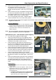
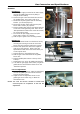
5. Remove the pilot burner shields from over the pilot
burners / thermocouples by removing the 2 screws securing
the pilot burner shields to the splash guards. (Refer to Fig
17).
6. Remove the splash guards covering the burner manifolds by
unscrewing the two allan headed screws. Carefully remove
the splash guards taking care not to damage the pilot
burners and thermocouples protruding through the splash
guard.
Main Injectors
a. Unscrew and remove the main injectors (½" A/F) from
the gas cocks.
b. Replace with the correct size injectors. Refer to the ‘Gas
Specifications Table’ at the end of this section and the
Rating Plate for correct injector sizes for the
corresponding gas.
• For Bench, Cabinet Base and Leg Stand Models,
the Rating Plate is attached to the underside of the
right hand side, front Cooktop lower trim.
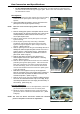
Gas Conversion and Specifications
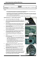
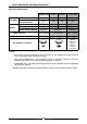
Manifold Test
Point
Low Fire Adjustment Screw
Fig 15
2 Pilot Burner
Shield Screws
Fig 16
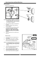
Fig 17
Main Injector
Pilot Injector
Plug
Fig 18
Pilot Burner
Shield