
User's Manual


User Manual • Expanded Calibration Guide • Page 11
USER MANUAL • 9 • EXPANDED CALIBRATION GUIDE
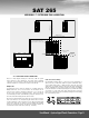
SAT 265
Instructions for electroacoustic calibration of a 2.1 audio system
using a SPL meter and Blue Sky’s test files.
Before starting this procedure you will need to download BlueSkyTestFiles.
zip (an 18 MB zip file) by going to www.abluesky.com website. To download
the test file, “Right Click” and select “Save Target As”. The file will begin
downloading once a location has been selected.
Once downloaded, either burn the test files to a CD or import them into your
DAW and follow the instructions below.
ADDITIONAL REQUIRED ITEMS
1. 2.1 Monitoring System
2. SPL Meter - such as the SPL meter sold by
RadioShack in the U.S.
BlueSkyTestFiles.zip Includes 4 files:
• 1000Hz SINEWAVE -20dBFS.wav – a 1kHz file recorded at -
20dBFS for electrical calibration
• 40-80Hz PINK NOISE -20dBFS.wav – a 40Hz to 80Hz bandwidth
limited pink-noise file recorded at -20dBFS
• 500-2.5kHz PINK NOISE -20dBFS.wav – a 500Hz to 2.5Hz
bandwidth limited pink-noise file recorded at 20dBFS
• Pink Noise full bw -20dBFS.wav – a full-bandwidth pink-noise file
recorded at - 20dBFS
These test files are all mono files. Please make sure you hard assign them
to the left and then the right, not both channels at the same time. If you are
using a CD player use only one channel of the CD player.
THEORY
The purpose of calibration is to adjust the overall electroacoustic system
gain so that 0dBVU of electrical signal level equals a certain acoustic level
at the listening position. Since most recording media is now digital, the
reference electrical signal level is usually –20dBFS with 20dB of headroom.
The reference SPL level however can vary based on the delivery media and
speaker type.
Please note that the bandwidth limited signals that have been provided, limit
many of the room interaction affects often associated with measuring SPL
and broadband pink noise.
All test signals are recorded at –20dBFS including the 1 kHz sine wave tone.
The sine wave tone is used to set the electrical output level throughout the
signal path, right up to the point you get to the speakers, while the various
pink noise signals are used for acoustic measurements and calibration.
The following procedure assumes you are calibrating the system to 85dBc
SPL.
Step 1 TURN OFF THE MONITORING SYSTEM (until step 4)
Step 2 Remove all eq and dynamics from the signal path and set all
controls to zero / unity gain. Play the 1kHz Sine Wave, hard
assign it to the left channel only, and adjust the output fader
so the output meter reads -20dBFS. If you are using an analog
console, set the output level to 0 VU. Then hard pan the signal to
the right channel output and repeat for the right channel. Once
calibrated do not move the output faders.
Step 3 Mute everything
and make sure the 1kHz tone is OFF .
Step 4 Now that the system has been electrically calibrated
turn
ON the SAT 265 / SUB 212 2.1 Monitoring System.
Step 5 Assign the 500-2.5kHz pink noise signal to the left channel only.
Make sure there is nothing coming from the right channel (or any
other channels). Because this signal is bandwidth limited, you
don’t have to worry about turning the sub off.
There are two methods of setting the levels:
A. If you have a master monitor level control (console etc), you
can set the SAT 265 gain control at reference and then adjust the
monitor gain control for 85 dBc. Then mark the monitor level as
your reference position.
B. The other method is to set master monitor level (console etc.)
to the position you want reference level to be (such as unity gain
as determined by the electrical calibration process in beginning
of these instructions) and then use the volume control on the
SAT 265 to set 85 dBc. If you use this method you should make
a note of the positing, so you can always go back to the new
“reference level” if the pot gets moved.
For either method:
SPL should be measured at the mix position, with the SPL meter
at arms length, with the microphone at seated ear height, angled
at approximately 45 degrees, and pointed at the center point
between the left and right speakers.
Once the left channel is set to 85dBc, repeat this step for the
right channel
Step 6 Feed 40-80Hz pink noise signal to the left channel only. Adjust the
subwoofer level control until the subwoofer reads 85dBc (slow)
at the mix position. The meter will bounce around a little, so you
will need to do a mental average (
I tend to filter out the peaks in
my mind, so I don’t set the sub too hot
). The right channel should
measure about the same and no additional adjustments need to
be made.
Step 7 You can play the full-bandwidth pink noise, assigning it to the left
and then the right channel (not at the same time). You should
measure about 85dBc. It may be a little higher, because below
30Hz the room may have a little extra gain. No adjustments
should be made with Full Bandwidth pink noise, unless you have
an RTA (real time analyzer) or other spectrum analyzer.
Step 8 The calibration process has now been completed. Congratulations!
If you have any questions, please do not hesitate to contact us
directly with your questions. (516) 249-1399 (9:00am to 5:30pm
EST) or visit our website / forum @ www.abluesky.com.