
User's Manual


User Manual • A Tour of the SAT 265 Amplifier & Electronics • Page 7
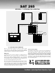
1. XLR INPUT - This XLR input should be connected to a bass-
managed output with a 12 per octave 80Hz high-pass filter, such
as the bass-managed outputs on the SUB 15 Universal, SUB 212,
SUB 12, or BMC. This input is electronically balanced. Do not
connect more than one source to this input. Refer to page 5
[SAT 265 Feature Overview] and page 9 [System Signal Flow &
Connections] for more information.
2. Rear Power LED - This power LED indicates the SAT 265 is
powered ON.
3. GAIN - This trim pot is a continuously variable gain control, with a
range of -12 to REF (200mV of 500 to 2kHz pink noise = 90dB
SPL @ 1M). In combination with the -10dB input pad, this allows
for a range of -22dB to REF. Please refer to page 5 for more
information [SAT 265 Feature Overview].
4. XLR INPUT 0dB / -10dB Dip-Switches - These dip-switches control
the 10dB input “pad” on the 80Hz Input. With both dip-switches
in the UP position, the -10dB pad is in circuit. With both switches
in the down position, it is out of circuit. Max input in the 0dB
position is +14 dBu, in the -10dB position it is +24 dBu. Refer to
page 5 for more information [SAT 265 Feature Overview].
5. Baffle Compensation Dip Switches - The SAT 265 includes four
primary baffle compensation settings, each of which reduces the
MF to LF “bump” that typically results from mounting a speaker
in a baffle wall. To select a specific setting, put the individual
dip switch into the “UP” position. For additional flexibility, baffle
compensation switches can be used in combination.
The amount of compensation needed is dependent on room
acoustics, along with the size and type of baffle wall. The only
way to accurately determine the amount of compensation needed
is to use a high resolution acoustic analyzer, such as MLSSA,
TEF, etc.
6. Tweeter Level Controls - The SAT 265 includes +/- 3dB of
tweeter level adjustments, in 1dB increments. The switches are
additive, so in order to increase the level of the tweeter by 3dB
set both the 2 and 1dB switches to the UP position. We highly
recommend that you only change these settings, from the “flat”
position, as a last resort and only after doing proper acoustics
treatment of the room and ensuring proper placement of the SAT
265. For more information please see page 5 [SAT 265 Feature
Overview] and page 14 [Measurement Data].
7. Power Switch - Controls the power to all the three amplifiers and
all internal electronics.
8. Voltage Selector Switch - This switch can be set to either 115
Volts or 230 volts. Prior to powering this unit, please confirm that
the Voltage selector switch has been set to the correct voltage
setting. If you are unsure of the type of power that is supplied to
your studio, consult your product dealer or local power company.
If your changing the Voltage, please also confirm the proper fuse
is installed [see number 10].
9. FUSE - Replace with same rating and type for your local voltage
rating. For 115V applications use a 6 Amp T 250V and for 230
Volt applications use a 5 x 20mm, 3.16 Amp, T 250V fuse (“T” =
Time Delay or SloBlo type fuse).
10. IEC RECEPTACLE - Check voltage selector switch before
connecting power. Connect to 115 Volt AC / 60Hz power source,
rated for 375 WATTS or 230 Volt / 50Hz rated for 375 WATTS.
11. Amplifier Heatsink - The heatsink provides essential cooling to
the amplifiers inside the SAT 265. This heatsink is oversized and
designed to be effective in both vertical and horizontal orientation,
as long as proper air circulation is provided. Please ensure that
proper air circulation is available for cooling. This is especially
important when baffle mounting the SAT 265.
USER MANUAL • 5 • A TOUR OF THE SAT 265 AMPLIFIER & ELECTRONICS
SAT 265