
User's Manual


Page 8 • User Manual • Mounting & Placement
Monitor mounting and placement is often an afterthought, but in order to get
the best imaging and overall performance from the SAT 265, it is important
to place the speakers correctly.
Monitoring Height:
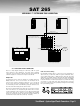
Figure 1 shows the ideal monitoring height, with the SAT 265
located perfectly at seated ear height, with the cabinet in
recommended vertical configuration. If this is not possible, tilting
or aiming the cabinet at the listening area can improve high-
frequency coverage.
Monitoring Angle:
The recommended position for the monitors is based on an ITU
standard and sets the speakers at 60 degrees from the listener,
forming an equilateral triangle (a triangle with equal sides) - See
Figure 2. Fortunately, this setup eliminates most of the math and
is easily simplified to the following guidelines: If you want to sit 2
meters from the speakers, place the speakers 2 meters apart. If
you want to sit 9 ft. from the speakers, place the speakers 9 ft.
apart Etc.
Wall Mount Options:
The SAT 265 is compatible with OmiMount® 60 Series brackets,
via the 1/4 X 20 inserts located on the bottom of the cabinet.
The OmniMount® 60 brackets are designed to support up to
60 pounds of weight when properly installed. Please visit www.
omnimount.com for more information, including detailed mounting
instructions. Please see page 13 [Technical Specifications &
Dimensions] for more information on insert locations. Also see
page 3 [Safety Instructions] item 17 “MOUNTING”.
Mounting the SAT 265 in a baffle wall / soffit:
IMPORTANT: It is highly recommended that you check all of your
local electrical and safety codes, to make sure that all regulations
are going to be met before mounting the SAT 265 in a baffle
wall.
Requirements and recommendations:
1) Important Requirement: Proper cooling and airflow shall be
provided to the back of the SAT 265 / Heatsink.
2) Recommendation: In order to build an affective baffle wall,
it is best to use a design with considerable mass, that doesn’t
produce sympathetic resonances. Using three layers of 5/8” (50
mm) Gypsum, with overlapped joints, and the appropriate wood
framing has been found to be affective (again, consult local
building codes and an engineer or architect for specific design
guidelines).
3) Recommendation: To avoid sympathetic vibrations, it is best
to physically decouple the SAT 265 from the baffle wall structure.
An effective way to do this is to use Mason Super W neoprene or
natural rubber pads (durometer 40). One Super W pad should be
placed under each corner of the speaker.
4) Recommendation: Mount the SAT 265 flush with the front of
the baffle wall and seal all gaps around the SAT 265 and the
baffle wall using a rubber, foam or neoprene gasket material.
This will improve the HF frequency response, by reducing any
cabinet or edge diffraction related problems (again, check local
building codes).
5) Recommendation: The SAT 265 includes four primary baffle
compensation settings, each of which reduces the MF to LF
“bump” that typically results from mounting a speaker in a baffle
wall. The amount of compensation needed is dependent on room
acoustics and the size and type of baffle wall. The only way to
accurately determine the amount of compensation needed is to
use a high resolution acoustic analyzer, such as MLSSA, TEF, etc.
For more information please see page 6 & 7 [A Tour of the SAT
265 Amplifier & Electronics].
Mounting the SAT 265 behind an acoustical transparent screen:
If you intend to place the SAT 265 behind an acoustically transparent
screen, it is recommend that you use a screen that provides the
minimum amount of acoustic loss at high frequencies, such as
the Microperf screens offered by Stewart Filmscreen (www.
stewartfilmscreen.com). Additionally, it is also recommended
that you add some acoustically absorptive material to the front
of the wall behind the screen, to help absorb HF reflection from
the screen. Typically 2” of black duct liner, or other fiberglass
acoustical blanket can work well (check local building and safety
codes for possible restrictions and guidelines).
FIGURE 1
FIGURE 2
MONITORING HEIGHT
RECOMMENDATIONS
Center of the woofer
Center of the tweeter
USER MANUAL • 6 • MOUNTING & PLACEMENT
SAT 265